
Coordinate input device and terminal device having the same

一种坐标输入装置、终端装置的技术,应用在数据处理的输入/输出过程、仪器、电数字数据处理等方向,能够解决成本成为问题、得不到充足光量等问题,达到高效照明、提高用户便利性的效果

Inactive Publication Date: 2008-06-11
ALPS ALPINE CO LTD
View PDF5 Cites 0 Cited by
  • Summary
  • Abstract
  • Description
  • Claims
  • Application Information

AI Technical Summary

Problems solved by technology

Therefore, since the light of the backlight is absorbed by the LCD or the sensor, there is a problem that a sufficient amount of light cannot be obtained.
In addition, the sensor needs to be made of a light-transmitting material, which also poses a problem in terms of cost

Method used


Image

  • Coordinate input device and terminal device having the same
  • Coordinate input device and terminal device having the same
  • Coordinate input device and terminal device having the same

Examples


Embodiment Construction

[0022] Hereinafter, embodiments of the present invention will be described in detail with reference to the drawings.

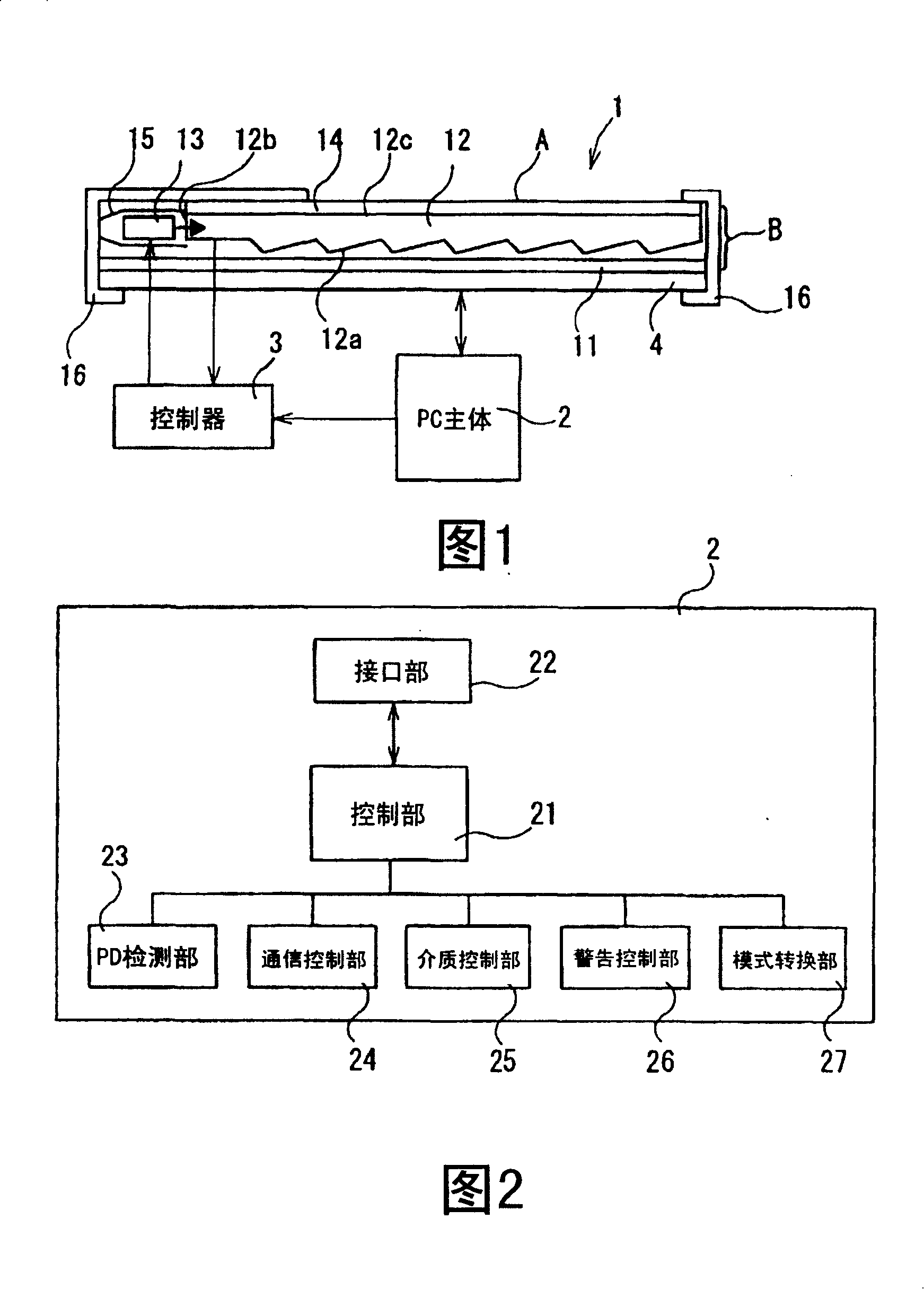
[0023] FIG. 1 is a diagram showing a schematic configuration of a terminal device including a coordinate input device according to an embodiment of the present invention.

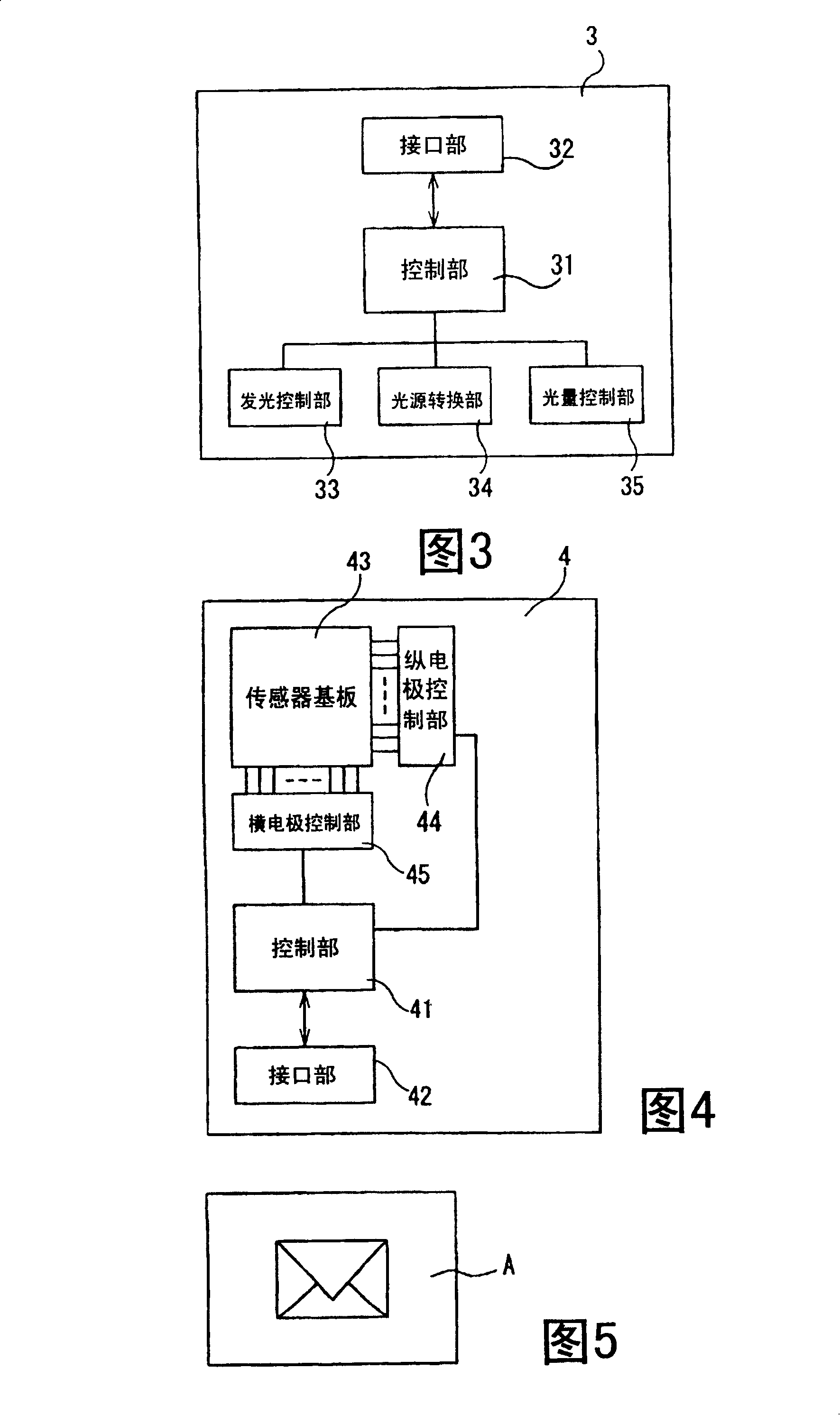
[0024] The terminal device shown in FIG. 1 has an operation surface operated by a coordinate indicating body such as a user's finger, and mainly includes: a coordinate input device 1 capable of illuminating the operation surface with a light source; A personal computer (PC) body 2 for instructing input from the coordinate input device 1 , and a controller 3 for controlling a light source of the coordinate input device based on the functions of the coordinate input device 1 and the PC body 2 . The coordinate input device 1 is embedded and installed in the PC main body 2 .

[0025] The coordinate input device 1 is composed of a sensor 4 and a front light (front light) B. The sensor 4 is a de...


PUM


Abstract

A coordinate input unit is composed of a sensor as a means for detecting a manipulating state on a manipulation surface A manipulated by a coordinate indicator and a front light as an illumination means disposed on the sensor to illuminate the manipulation surface A. When the manipulation surface of the coordinate input device is illuminated, the light emitted from an LED is transmitted in a light introduction plate, emerged from a prism surface, changes its direction by being reflected on a reflection plate, and is directed to the manipulation surface. With this operation, the manipulation surface is illuminated.

Description

technical field [0001] The present invention relates to a coordinate input device and a terminal device with the coordinate input device, in particular to a coordinate input device with a light emitting function and a terminal device with the coordinate input device. Background technique [0002] Currently, a coordinate input device called a touch panel is mounted on a portable computer terminal device such as a notebook computer. The touch panel is a pointing device for operating the cursor and pointer displayed on the screen of the terminal device in the same way as a mouse. Move the coordinate value or contact point, and operate the cursor and pointer according to the displacement of the coordinate value. [0003] In such a coordinate input device, a sensor is made of a translucent thin plate, and a color LCD panel with a backlight is arranged below the sensor to illuminate the operation surface. [0004] [Patent Document 1] (Japanese) Unexamined Patent Publication No. ...

Claims


Application Information

Patent Timeline
Patent Type & Authority Patents(China)
IPC IPC(8): G06F3/033
CPCG06F3/044G06F3/041G06F3/0412G06F3/0446
Inventor 村上孝博重高宽
Owner ALPS ALPINE CO LTD
Learn More