Valve apparatus for heat transfer

A technology for valve devices and heat exchangers, applied in valve devices, fluid heaters, lift valves, etc., can solve problems such as increased cost of valve devices, and achieve the effect of small weight and low material consumption

Inactive Publication Date: 2008-06-11
DANFOSS AS
View PDF5 Cites 2 Cited by
  • Summary
  • Abstract
  • Description
  • Claims
  • Application Information

AI Technical Summary

Problems solved by technology

[0004] Although the application of a pressure regulating valve has a favorable effect on the control performance of the valve arrangement, it increases the cost of this type of valve arrangement

Method used


Image

  • Valve apparatus for heat transfer
  • Valve apparatus for heat transfer

Examples


Embodiment Construction

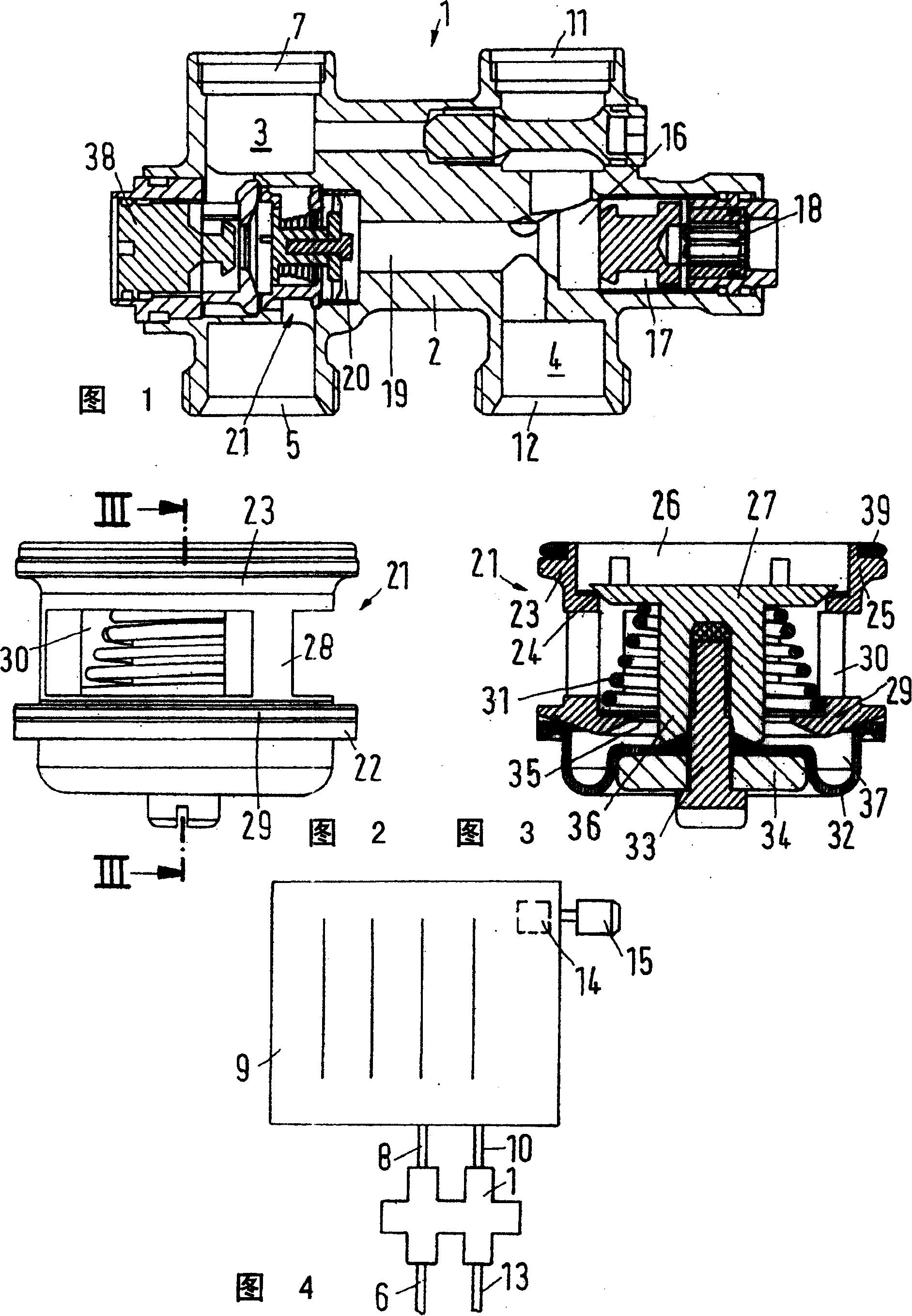
[0028] FIG. 1 shows an H-shaped piece 1 with a housing 2 having a forward path 3 and a return path 4 . The forward path 3 has an inlet 5 ( FIG. 4 ) for a building-fixed supply line 6 and an outlet 7 for a heating-body-side advancing line 8 which is connected to the heating body 9 . The heating body 9 is connected via a return line 10 to the inlet 11 of the H-shaped piece. The H-shaped part 1 has an outlet 12 which is connected to an outlet line 13 which is permanently installed in the building. A heating body valve 14 with a thermostatic valve attachment 15 is mounted on the heating body 9 at a location that is easily accessible.

[0029] The H-shaped part 1 has a connection 16 between the inlet 11 and the outlet 12 in the region of the return path 4 . An opening 17 leading to the outside is closed by a closure plug 18 . Here, of course, instead of the closing plug 18, a heater valve 14 can be installed so that it can regulate the flow of the heat transfer fluid flowing thr...


PUM


Abstract

Heat exchanger valve arrangement, especially for a radiator valve has a valve seat (24), valve element (27), spring element (31) and a pressure reaction apparatus (32), which serves to maintain a constant pressure across the valve, that are joined together by a single connection (33). The whole assembly then forms a single handheld unit that can be inserted into the valve housing.

Description

technical field [0001] The invention relates to a valve device for a heat exchanger, in particular a valve device for a heating body, having a housing with an inlet and an outlet, a regulating valve and a pressure regulating valve, the pressure regulating valve keeps the pressure in the valve device constant Change, and has a valve seat, a valve element, a spring member and a pressure response mechanism. Background technique [0002] A heater valve arrangement of this type is known from EP 0 911 714 A1. It is used, for example, in heating equipment in which many heating bodies are connected in series in the same heating pipeline. In known cases, the pressure regulating device keeps the pressure on the valve constant, so that other heaters connected to the same pipeline The influence of the body on the control performance of the regulating valve which is to control the inherent flow of the heat transfer fluid flowing through the heating body is kept very small. [0003] A p...

Claims


Application Information

Patent Timeline
Patent Type & Authority Patents(China)
IPC IPC(8): F16K17/04G05D16/06F24D19/10F16K1/00F16K11/10F24H9/12
CPCF16K17/048F24D19/1018F16K11/105F24D19/0012G05D16/0655G05D16/028
Inventor M·H·克里斯滕森
Owner DANFOSS AS
Why Eureka
Try Eureka