Therapeutic apparatus combining light and heat for curing prostate
A prostate treatment instrument, photothermal technology, applied in treatment, phototherapy, radiation therapy, etc., can solve the problems of inability to continuously adjust the treatment temperature and affect the treatment effect, and achieve the effect of compact structure, safe and reliable use, and obvious curative effect
- Summary
- Abstract
- Description
- Claims
- Application Information
AI Technical Summary
Problems solved by technology
Method used
Image
Examples
Embodiment 1
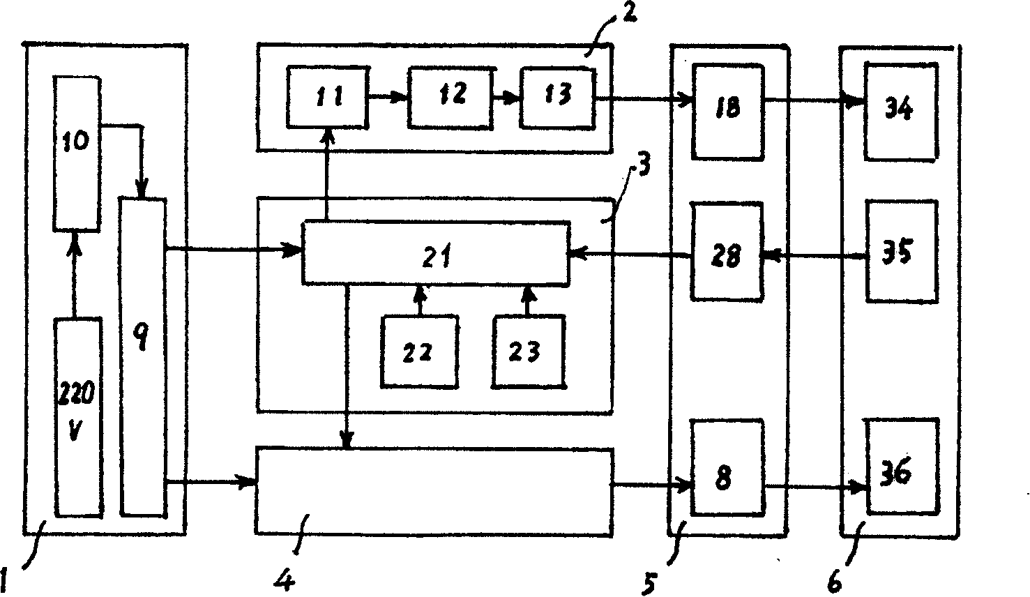
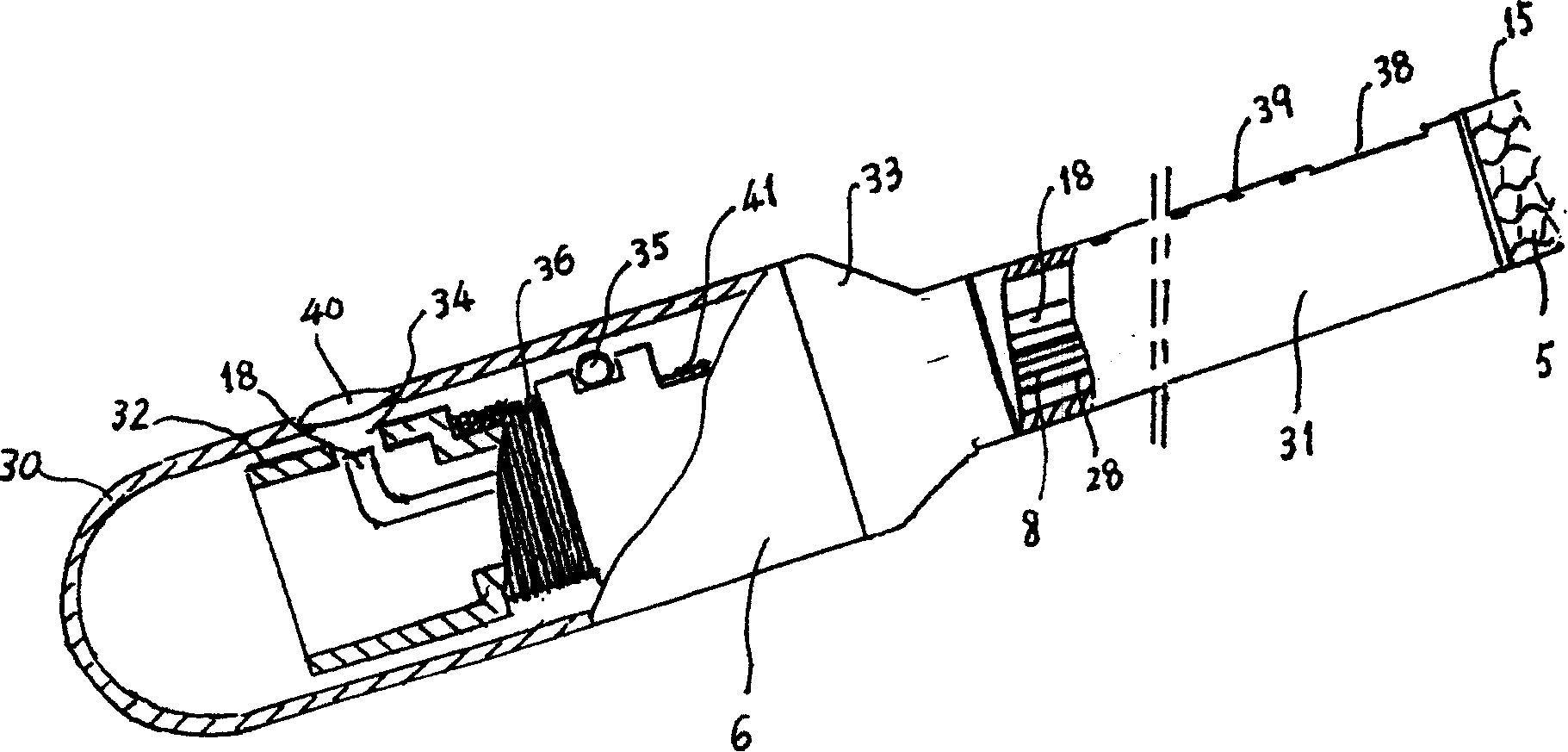
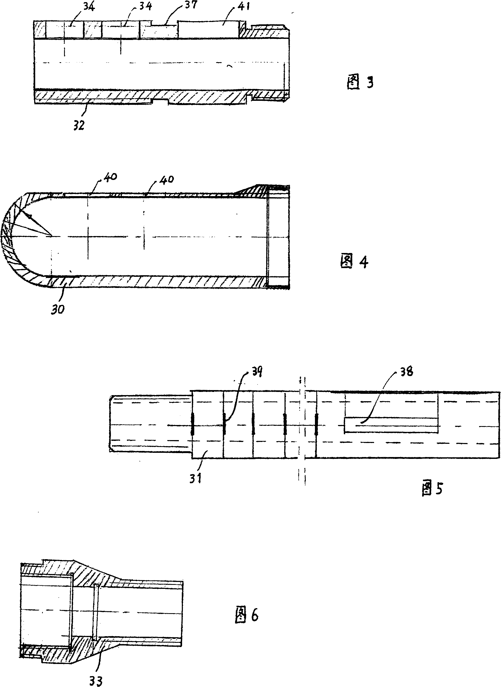
[0020] Embodiment 1 The laser system 2 is composed of two sets of He-Ne lasers, the length of the laser 13 is about 1m, and the terminal laser power is not less than 21mW per beam. The frame 32 and the jacket 30 of the treatment head 6 are given by FIGS. 3 and 4 . Correspondingly, two laser output windows 34 are arranged side by side on the side of the hollow frame 32; the groove 37 in the middle of the frame 32 is used to wind the heating wire, and the heating wire is the heat radiation element 36; 41 is the wiring port to facilitate heat radiation Component connection 8 and heat radiation temperature control connection 28 are electrically connected with heat radiation element 36 and temperature measuring element 35 at wiring port 41; When the frame 32 is fastened by the connecting head 33 , the laser output window 34 on the frame 32 is opposite to the lens 40 on the casing 30 one by one.
[0021] The top of the jacket 30 is hemispherical, and the inner helix at the end is s...
Embodiment 2
[0022] The structures of a handle 31 and a connecting head 33 of the treatment head 6 in Embodiment 2 are shown in FIG. 5 and FIG. 6 .
[0023] Wherein, the handle 31 is a hollow straight pipe. The side outer surface of the handle 31 has a laser light-emitting mark groove 38 and a scale 39 , and the laser light-emitting mark groove 38 and the scale 39 are on the same straight line as the lens 40 on the side of the overcoat 30 .
[0024] As shown in Figure 6, the hollow connector 33 has an inner helix and an outer helix at the larger end of the opening, which is used to screw the skeleton 32 and the overcoat 30; The laser light-emitting marking groove 38 and the scale 39 are on the same straight line as the lens 40 on the side of the jacket 30 . In this way, the output direction of the laser inserted into the abdominal cavity can be easily known during treatment, and the depth of the insertion of the treatment head 6 into the abdominal cavity can be easily known.
[0025] Con...
Embodiment 3
[0026] Embodiment 3 Infrared heat radiation temperature and treatment time are controlled by computer system 3 .
[0027] The temperature measuring element 35 is a Pt100 platinum resistance, installed on the frame 32, and is electrically connected with the computer 21 in the main box through the handle 31 and the optical fiber cable hose 5 through the handle 31 and the optical fiber cable hose 5 with the thermal radiation temperature control connection line 28. The treatment time selection 22 and the radiation temperature selection 23 issue instructions, and the infrared heat radiation temperature and working time are controlled through the computer 21 according to the information fed back by the temperature measuring element 35 . The control temperature range is 40-48°C, and the usual temperature is set at 45°C; the working time is adjustable from 0 to 60 minutes, and the usual time is 20 minutes.
PUM
 Abstract
Description
Claims
Application Information
 - R&D
- Intellectual Property
- Life Sciences
- Materials
- Tech Scout
- Unparalleled Data Quality
- Higher Quality Content
- 60% Fewer Hallucinations
Browse by: Latest US Patents, China's latest patents, Technical Efficacy Thesaurus, Application Domain, Technology Topic, Popular Technical Reports.
© 2025 PatSnap. All rights reserved.Legal|Privacy policy|Modern Slavery Act Transparency Statement|Sitemap|About US| Contact US: help@patsnap.com


