Development device and electronic photographing apparatus
A technology of electric potential and latent image, which is applied to equipment for electric recording technology using charge patterns, electrography, and electric recording technology using charge patterns, etc. It can solve image quality degradation, uneven thickness of toner layer, recording paper Stains and other issues
- Summary
- Abstract
- Description
- Claims
- Application Information
AI Technical Summary
Problems solved by technology
Method used
Image
Examples
Embodiment 1
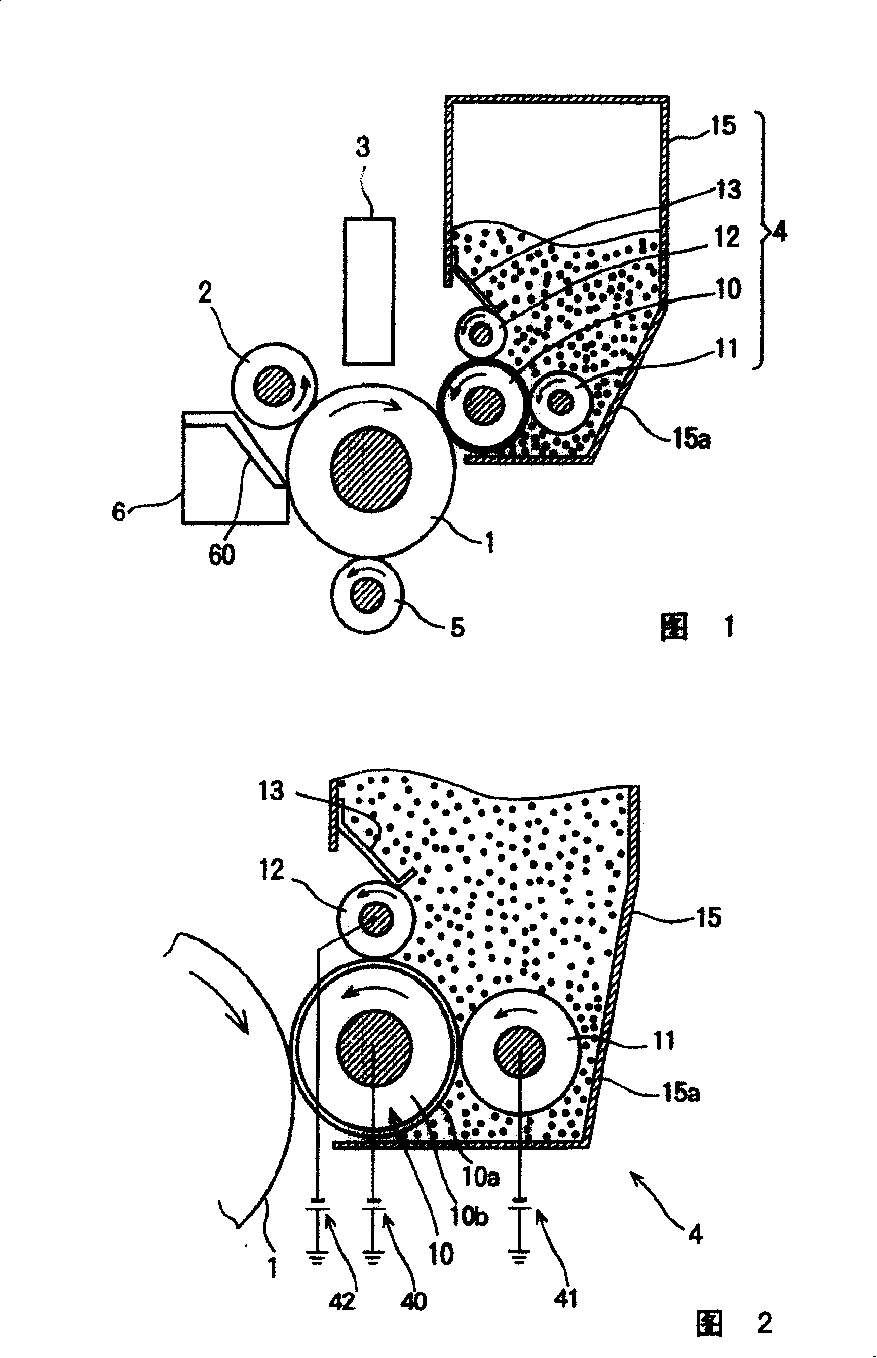
[0029] 1 is a sectional view of a main part of an electrophotographic apparatus including a developing device according to Embodiment 1. As shown in FIG. The electrophotographic apparatus is an electrophotographic apparatus of the type employing non-magnetic one-component image development. This electrophotographic apparatus includes a photosensitive drum 1 (hereinafter referred to as drum 1 ) as a latent image generating member. Formed on the peripheral surface of the drum 1 is a photosensitive layer which is insulating when it is not exposed to light and becomes conductive when it is exposed to light, thereby releasing charges therefrom. The drum 1 rotates in one direction (ie clockwise in Fig. 1). A charging roller 2 , a light emitting diode (LED) head 3 , a developing device 4 , a transfer roller 5 , and a cleaning unit 6 are arranged along the periphery of the drum 1 in the direction of rotation of the drum 1 .
[0030] The charging roller 2 is configured as a conductiv...
Embodiment 2
[0062] Figure 7 is an enlarged view of a developing device 4A according to Embodiment 2 of the present invention. In addition to the components of the developing device ( FIG. 2 ) of Embodiment 1, the developing device 4A has an auxiliary supply roller (a kind of auxiliary supply member) 16 adjacent to the toner layer forming roller 12 . The structure of the fixing device 4A is the same as that of the fixing device 4 of Embodiment 1 except that the auxiliary supply roller 16 is provided. The fixing device 4A is attached to the electrophotographic apparatus as described in Embodiment 1 (FIG. 1). The auxiliary supply roller 16 is provided inside the toner container 15 in contact with the right side of the outer peripheral surface of the toner layer forming roller 12 shown in FIG. 2 . The auxiliary supply roller 16 has a rotation axis parallel to the toner layer forming roller 12 and rotates in the same direction as the toner layer forming roller 12 . The auxiliary supply rol...
Embodiment 3
[0068] Figure 8 is an enlarged view of a fixing device 4B according to Embodiment 3 of the present invention. In addition to the components of the fixing device 4 ( FIG. 2 ) of Embodiment 1, the fixing device 4B has an additional supply roller (an additional supply member) 17 adjacent to the supply roller 11 . The configuration of the fixing device 4B is the same as that of the fixing device 4 of Embodiment 1 ( FIG. 2 ) except that the additional supply roller 17 is provided. The fixing device 4B is attached to the electrophotographic apparatus described in Embodiment 1 (FIG. 1).
[0069] exist Figure 8 , an additional supply roller 17 is provided inside the toner container 15 and in contact with the upper side of the outer peripheral surface of the supply roller 11 . The additional supply roller 17 has a rotation axis parallel to that of the supply roller 11 and rotates in the same direction as the supply roller 11 . Like the supply roller 11, the additional supply roll...
PUM
 Abstract
Description
Claims
Application Information
 - R&D
- Intellectual Property
- Life Sciences
- Materials
- Tech Scout
- Unparalleled Data Quality
- Higher Quality Content
- 60% Fewer Hallucinations
Browse by: Latest US Patents, China's latest patents, Technical Efficacy Thesaurus, Application Domain, Technology Topic, Popular Technical Reports.
© 2025 PatSnap. All rights reserved.Legal|Privacy policy|Modern Slavery Act Transparency Statement|Sitemap|About US| Contact US: help@patsnap.com


