Ribbed plate type heat exchanger with medium equipartition device

A technology for equalizers and heat exchangers, which is applied in the types of heat exchangers, indirect heat exchangers, and heat exchange equipment. The utilization and other issues to achieve the effect of strengthening the strength

Active Publication Date: 2008-05-14
无锡宏盛换热系统有限公司
View PDF6 Cites 0 Cited by
  • Summary
  • Abstract
  • Description
  • Claims
  • Application Information

AI Technical Summary

Problems solved by technology

[0003] Under normal conditions, the refrigerant medium in the refrigeration and heat pump cycle will not be automatically and evenly distributed to the layers between the heat exchange plates when it flows into the ribbed heat exchanger as the evaporator, which will cause the refrigerant medium to There is uneven evaporation in each evaporative heat exchange level of the ribbed heat exchanger, which will cause less cold medium in some heat exchange levels and too much cold medium in other heat exchange levels. The fins are not fully and effectively utilized in the heat exchange process, which affects and reduces the overall heat exchange effect of the ribbed heat exchanger
[0004] In order to solve the problem of uneven distribution of the cold medium in each heat exchange level of the ribbed heat exchanger, two published patents to solve this problem can be found in the Chinese patent data. They are: Patent No. 93121143.3 and Patent No. 96198973.4, the disadvantage of the patent No. 93121143.3 is that the cost of the patented technology is high and the refrigerant distribution device and the plug-in refrigerant medium distribution pipe are not easy to fix and assemble. The disadvantage of the patent No. 96198973.4 is that this can be evenly distributed The structure of the heat medium requires the diameter of the corner holes to be large, which is not convenient for use in ribbed heat exchangers with small corner holes.

Method used


Image

  • Ribbed plate type heat exchanger with medium equipartition device
  • Ribbed plate type heat exchanger with medium equipartition device
  • Ribbed plate type heat exchanger with medium equipartition device

Examples


Embodiment 1

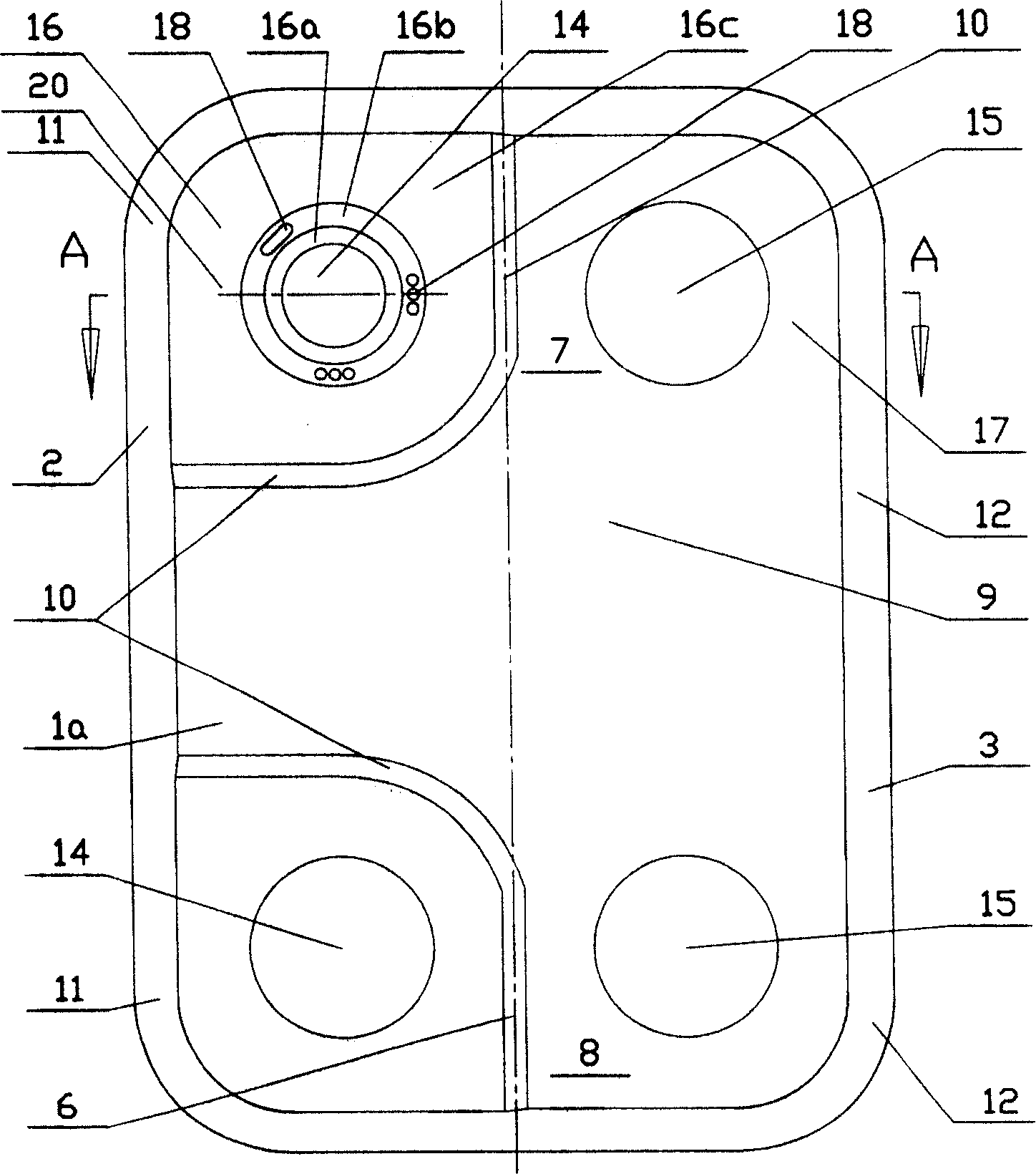
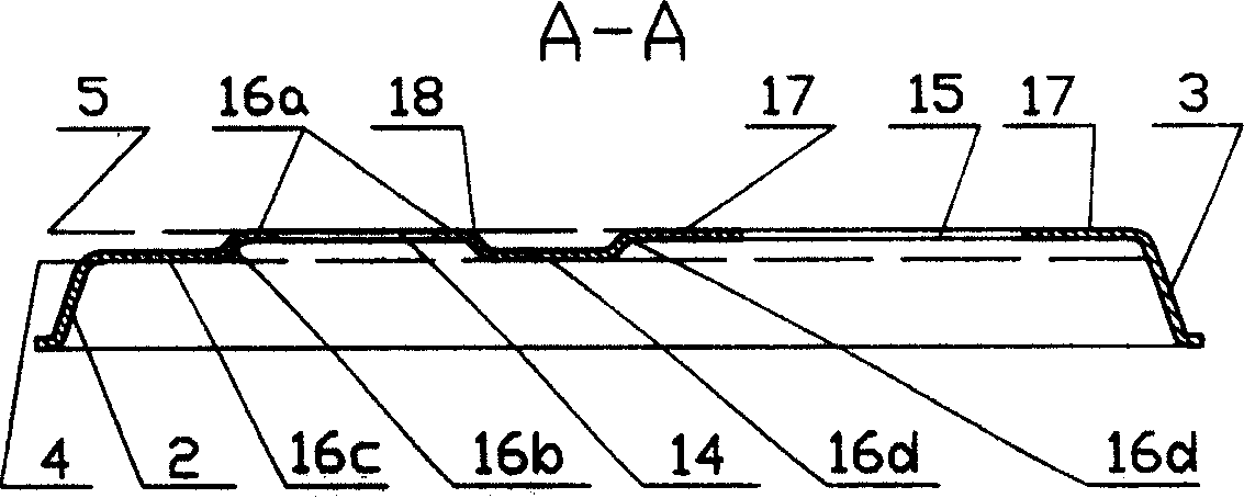
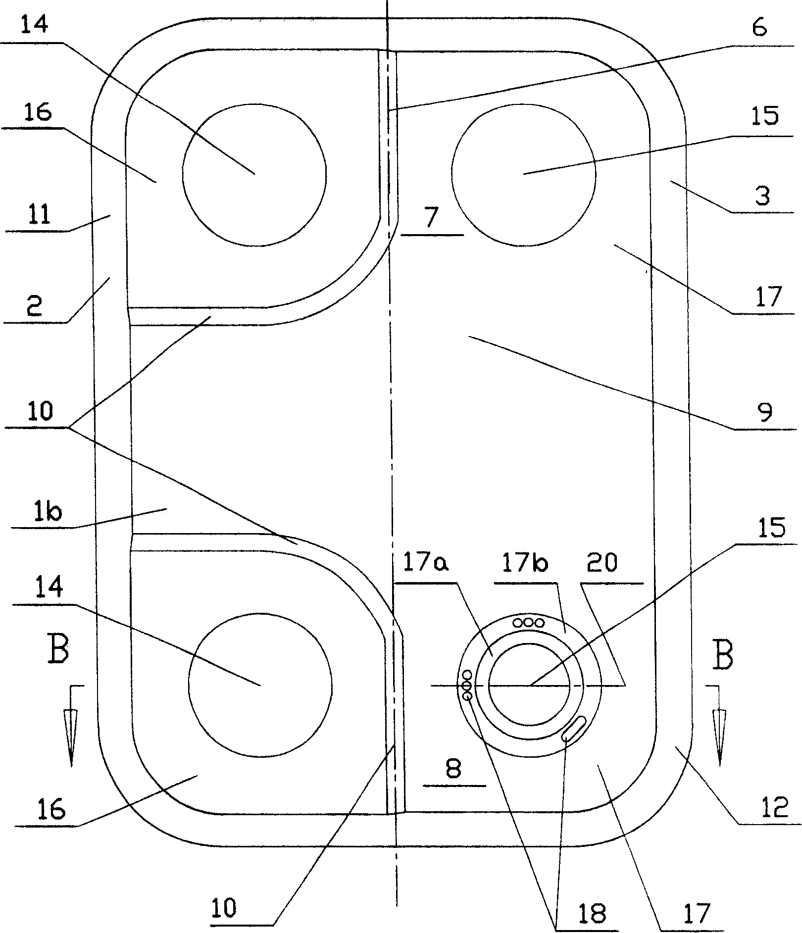
[0032] as attached figure 1 , 3 As shown, a ribbed heat exchanger with a medium divider includes at least two heat exchange plates 1a, 1b, and each heat exchange plate 1a, 1b is in the first edge area 2 and the second edge area 3 There is an extension of the upper plate plane 4 and the lower plate plane 5 parallel to each other, and the center line 6 divides the heat exchange plate 1a, 1b into a first part 11 and a second part 12, wherein each heat exchange plate 1a, 1b includes : a first end region 7; a second end region 8; a central heat transfer region 9 between the first edge region 2 and the second edge region 3 from the first end region 7 to the second end region 8 Extension; the first corner hole 14 and the second corner hole 15, which pass through the heat exchange plates 1a, 1b in the first end region 7 and the second end region 8 to form through holes and are respectively adjacent to the edge region Surrounding, wherein the first corner hole 14 is located in the fi...


PUM


Abstract

The invention relates to a rib heat exchanger, with lower cost. Wherein, it has a medium distributor, while it can be used in the heat exchange plate with small angle aperture; the first nearby edge of first angle aperture of first heat exchange plate via the first edge incline extends downwards to the second nearby edge; the second nearby edge extends rightwards to the central line, and via the incline transition section extends upwards to the be layered with the second angle aperture nearby edge; the first nearby edge of second angle aperture of second heat exchange plate via the first edge incline surface extends upwards to the second nearby edge; the second nearby edge extends left wards to the central line, and via the incline transition section extends downwards to be layered with the first angle aperture nearby edge; the first edge incline surfaces of said two heat exchange plates both have small holes, while they are alternatively layered.

Description

technical field [0001] The present invention relates to a ribbed heat exchanger, in particular to a ribbed heat exchanger used in evaporators in refrigeration and heat pump cycles. Background technique [0002] The ribbed heat exchanger used for evaporator in this type of refrigeration and heat pump cycle system is usually composed of heat exchange plates that are connected and sealed together. There is a heat exchange structure in the heat exchange plate, and the heat exchange plate There are corner holes and corner hole sealing surfaces at both ends. When the heat exchange plates are connected and sealed together as required, these corner holes will form a confluence flow channel for the heat exchange medium in the heat exchanger. Usually, these heat exchange plates The connection and sealing form of the plates adopts the welding or brazing process, but adhesive or sealing gaskets can also be used as the connection and sealing form between the heat exchange plates. [000...

Claims


Application Information

Patent Timeline
Patent Type & Authority Patents(China)
IPC IPC(8): F28F3/08F28D9/00
Inventor 缪志先凌祥钮法清
Owner 无锡宏盛换热系统有限公司
Why Eureka
Try Eureka