Method for manufacturing cross winding bobbin

A cross-winding bobbin and bobbin technology, applied in the direction of thin material handling, conveying filamentous materials, transportation and packaging, etc., can solve the problem of reduced receiving volume, to avoid excessive load, stable performance, and avoid discontinuity sexual effect

Inactive Publication Date: 2008-04-30
SAURER GERMANY GMBH & CO KG
View PDF5 Cites 0 Cited by
  • Summary
  • Abstract
  • Description
  • Claims
  • Application Information

AI Technical Summary

Problems solved by technology

[0015] The disadvantage of this double-conical cross-wound bobbin is that its receiving capacity is significantly reduced

Method used


Image

  • Method for manufacturing cross winding bobbin
  • Method for manufacturing cross winding bobbin

Examples


Embodiment Construction

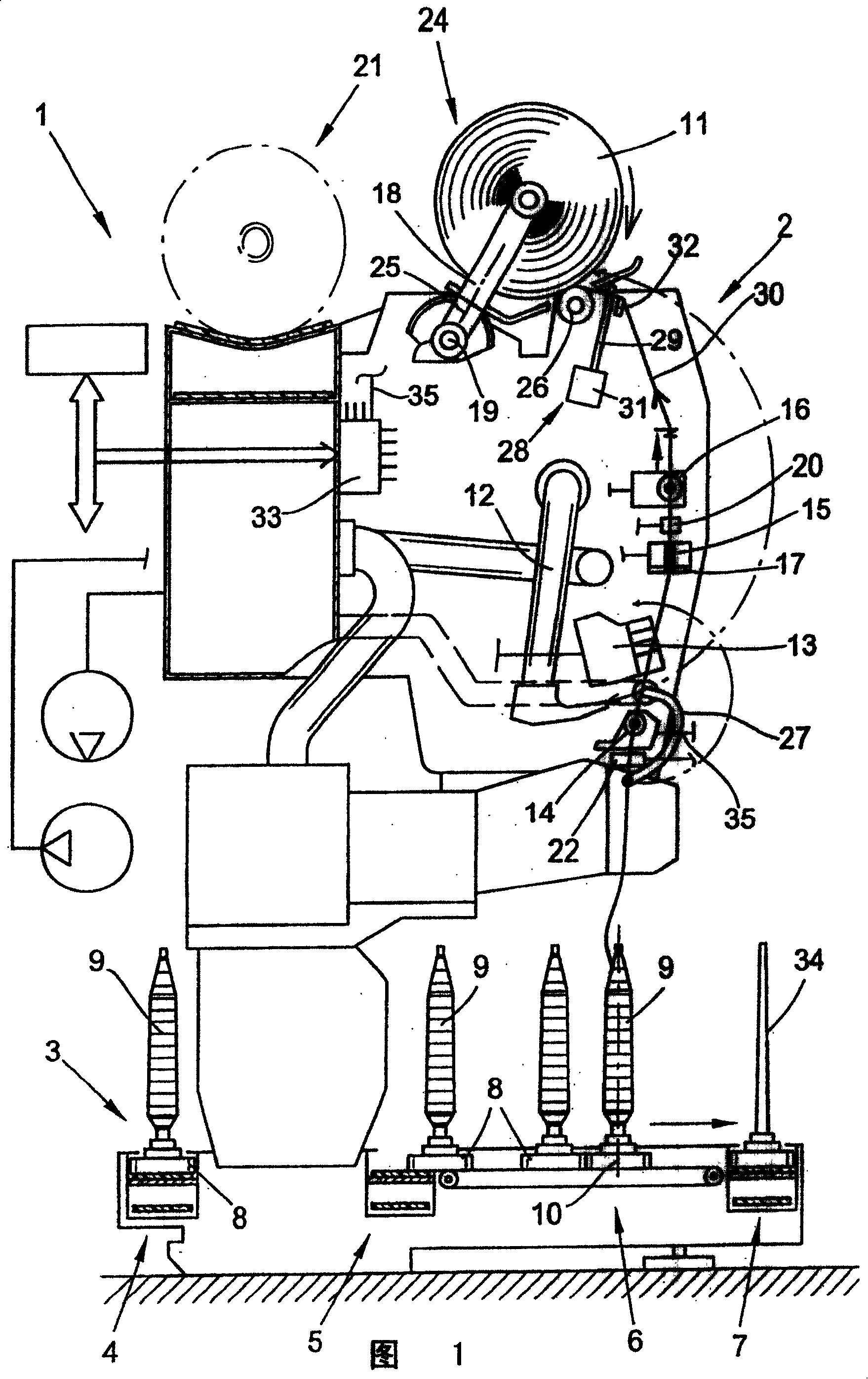
[0037] FIG. 1 schematically shows a spinning machine for the manufacture of cross-wound bobbins, which in the present embodiment is an automatic cross-winding device, which is generally indicated by reference numeral 1 in the figure. This cross-winding automatic equipment usually has several identical stations 2 (this is a known technology, not shown in detail) between its two end frames (not shown in the figure). Cops 9 produced on-machine are wound into large cross-wound bobbins 11 at said station.

[0038] After production, the cross-wound bobbin 11 is transported, for example by swiveling the creel around the pivot axis 19, to a cross-wound bobbin conveyor 21 in the longitudinal direction of the machine and to a machine end-side (Fig. not shown in ) bobbin loading station or similar.

[0039] Furthermore, such a cross-winding robot 1 usually has a logistics supply in the form of a bobbin transport system 3 . Cops 9 or empty bobbins, which are inserted vertically on the t...


PUM


Abstract

To produce a cross wound bobbin (11), at the workstation (2) of a bobbin winder (1), the yarn (30) is wound at the start of a winding cycle at a crossing angle to increase the density of the bobbin core. The crossing angle is increased significantly during the winding cycle, so that the density of the wound bobbin is reduced progressively outwards. The increased crossing angle acts against the yarn laying width, and the stroke movement of the reciprocating yarn guide (29) has a defined increase.

Description

technical field [0001] The present invention relates to a method of making cross-wound bobbins. Background technique [0002] Such cross-wound bobbins are formed, for example, on automatic cross-winding machines. That is to say, at the station of the textile machine relatively small bobbins, which are preferably spun on a ring spinning machine, are wound into large cross-wound bobbins. In addition, yarn inhomogeneities are detected during said winding process so that bad yarns are removed. [0003] In order to enable the orderly processing of such cross-wound bobbins in subsequent processes, such cross-wound bobbins should have good unwinding properties. The unwindability of cross-wound bobbins can be affected, for example, by the way the yarn layers are displaced during manufacture. Yarn layer displacement methods are divided into two categories, the so-called "rough winding" and "fine winding". [0004] The above-mentioned winding types have a long history and are desc...

Claims


Application Information

Patent Timeline
Patent Type & Authority Patents(China)
IPC IPC(8): B65H54/06B65H54/38B65H55/04
CPCB65H54/385B65H2701/31B65H54/06B65H55/04B65H2515/12
Inventor M·格里-莱费尔德
Owner SAURER GERMANY GMBH & CO KG
Why Eureka
Try Eureka