
Method for visual guiding by manual road sign

A visual navigation and road sign technology, applied in the field of artificial road sign visual navigation, can solve problems such as difficult control, inconvenient application of logistics robot control, and complicated goal setting

Inactive Publication Date: 2008-02-20
NORTHEASTERN UNIV LIAONING
View PDF3 Cites 2 Cited by
  • Summary
  • Abstract
  • Description
  • Claims
  • Application Information

AI Technical Summary

Problems solved by technology

Compared with artificial landmark navigation, visual navigation based on natural landmarks has complex goal setting and difficult control, and it is difficult to realize precise control of robots, which brings inconvenience to the control application of logistics robots.

Method used


Image

  • Method for visual guiding by manual road sign
  • Method for visual guiding by manual road sign
  • Method for visual guiding by manual road sign

Examples


Embodiment Construction

[0047] The artificial road sign visual navigation method of the present invention is described in detail in conjunction with the accompanying drawings.

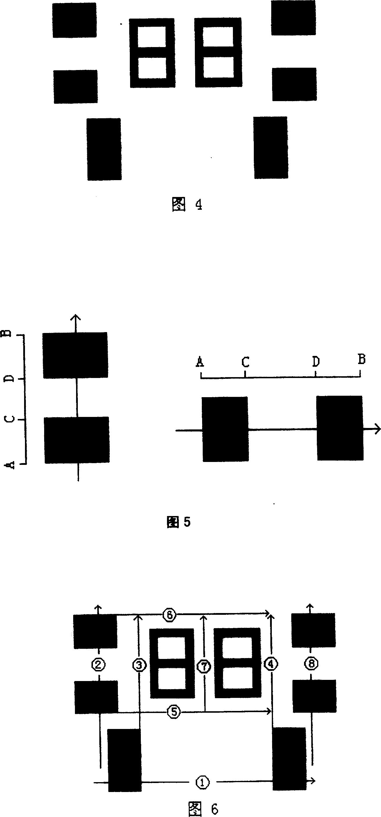
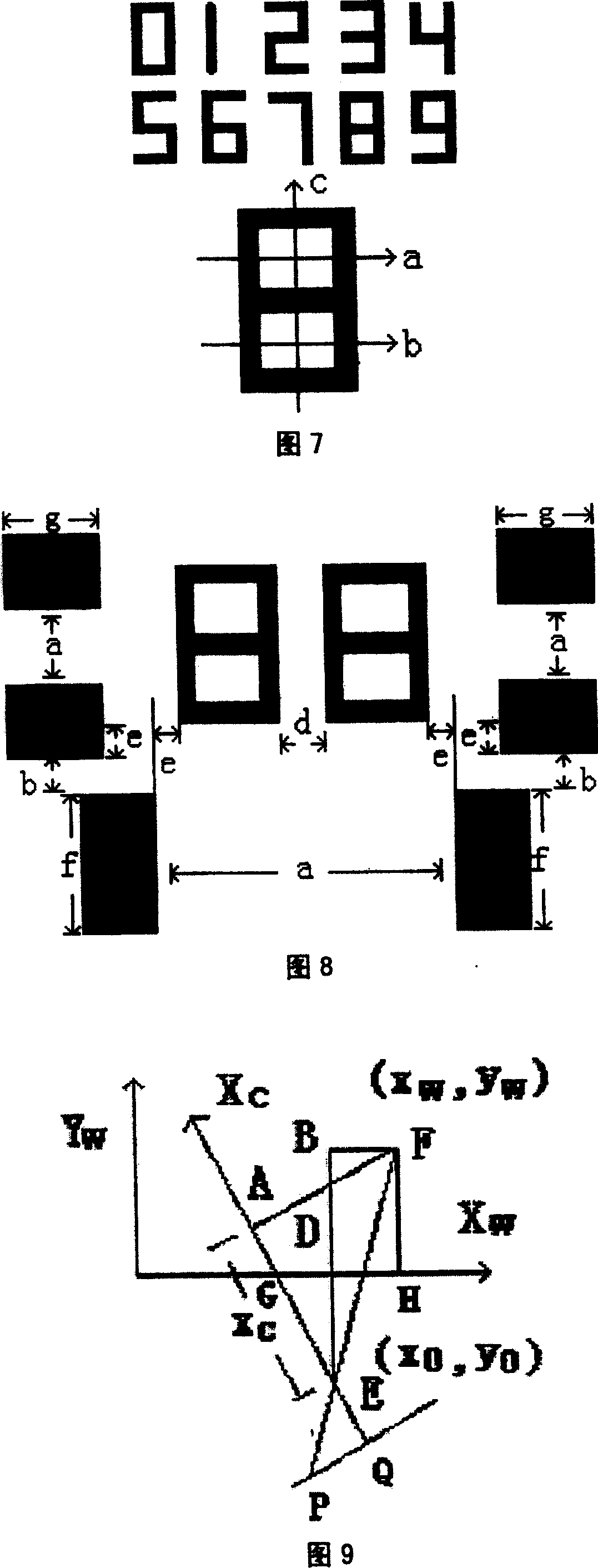
[0048] Signpost pattern design description:

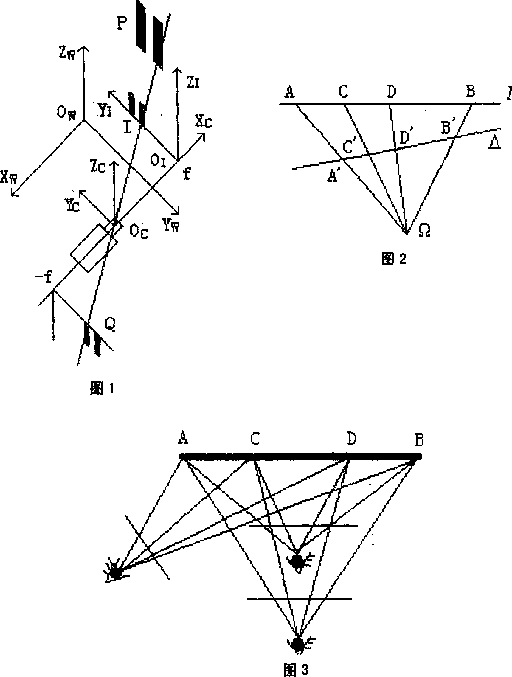
[0049] Another advantage of using the black bars to construct the complex ratio is that it can be proved that the complex ratio remains unchanged in the inclined state, that is AC CB AD DB = MP PN MQ QN , Thus, the stability of road sign detection is enhanced.

[0050] Although this kind of road sign cannot solve the problem of partial occlusion, in the case of many road sign modes, the occlusion problem is not important. If this is blocked, it can also be positioned from other road signs in the image.

[0051] In practical applications, the image resolution and road sig...


PUM


Abstract

The invention relates to an information technology automatic control field, the method is made up of road sign designing method, road sign position, road sign incriminating and navigating device, and road sign incriminating and control flow. The road sign designing method is a gray mode road sign, which is made up of two long black bar with the same width, four transverse long black bar with the same width and the middle numbers, the printed road sign is pasted on the plane vertically to the ground, such as the wall or side surface of computer desk, the height is similar to the camera height of robot, the incriminating and navigating device is only robot with a single camera, finally, it is accomplished road sign incrimination and control flow. The flow carries on binarization to the 256 gray images, then it is scanned and detected, finally the road sign number can be incriminated; the mode is simple, and the cost is low.

Description

technical field [0001] In the field of automatic control of information technology, it is suitable for use in the navigation of various logistics robots. Background technique [0002] At present, the positioning and navigation of autonomous mobile robots is an important research direction in the field of intelligent robots, and it is also a key technology of intelligent mobile robots. For this reason, various positioning and navigation technologies and vehicle-mounted sensor systems have emerged one after another. The main methods are: rely on the compass, odometer, etc. to give the relative positioning system of the approximate position and direction of the mobile robot; use sonar to establish a local scene model by measuring the distance between the scene and the robot; Or the magnetic strip on the ground constitutes the movement path of the robot to constrain the robot to walk along the magnetic strip. This method is mostly used in industry, but the disadvantage is that ...

Claims


Application Information

Patent Timeline
Patent Type & Authority Patents(China)
IPC IPC(8): G01C21/00E01F9/00G06K9/46G01C21/26G05D1/00
Inventor 郭阳方正徐心和
Owner NORTHEASTERN UNIV LIAONING
Learn More