Heating device for automatic anode linkage of MEMS high-temperature pressure sensor

A pressure sensor and anodic bonding technology, which is applied in semiconductor/solid-state device manufacturing, electrical components, circuits, etc., can solve the problems of poor heat resistance and complex body structure of peripheral devices, and achieve the effect of improving production efficiency

Inactive Publication Date: 2008-01-16
HARBIN INST OF TECH
View PDF6 Cites 0 Cited by
  • Summary
  • Abstract
  • Description
  • Claims
  • Application Information

AI Technical Summary

Problems solved by technology

(4) The complex body structure, coupled with the poor heat resistance of peripheral devices, brings new problems to heat insulation

Method used


Image

  • Heating device for automatic anode linkage of MEMS high-temperature pressure sensor

Examples


Embodiment Construction

[0013] The present invention is described in more detail below in conjunction with accompanying drawing example:

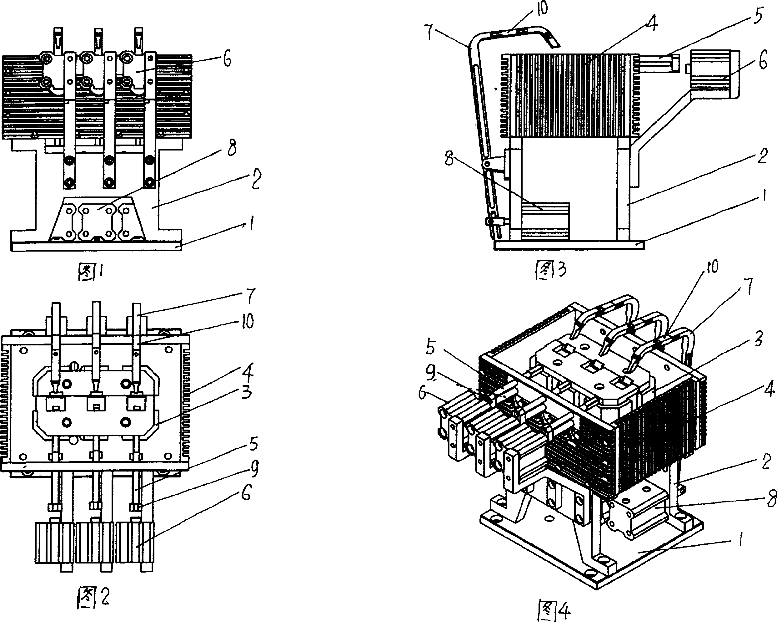
[0014] The composition of the heating device for automatic anode bonding of MEMS high-temperature pressure sensors includes a base plate 1, a support 2 is installed on the base plate, a heating block 3 is installed on the support, and heat sinks 4 are arranged around the heating block. There are round holes for heating rods and temperature sensors. The heating rods and temperature sensors are installed in the heating block. A clamp 5 and a clamp cylinder 6 matching the clamp are set on one side of the heating block. There is a return spring on the clamp. The other side of the package head 7 and the package head driving cylinder 8 are arranged, and there are heat-insulated connectors 9 and 10 between the clamps, the package head and their connectors. Multiple heating rods and temperature sensors are arranged on a heating block, the number of clamps, clamp cylinders...


PUM


Abstract

The heating unit includes floor plate. A support is installed on the floor plate. Heat blocks are installed on the support. Thermal fins are setup around the heat blocks. Heating rod and temperature sensor are installed on installation round holes on the heat blocks. Clamp and clamp cylinder assorted to the clamp are located at one side of the heat blocks. There is reset spring on the clamp. Packaging head and actuating cylinder of packaging head are located at another side of the heat blocks. Insulation connector is between clamp, packaging head and their connecting pieces. The invented heating unit is based on PC controlled multiple linkages. Chip linkage function is carried out at multiple processing points under control of upper computer so as to raise production efficiency greatly.

Description

(1) Technical field [0001] The invention relates to a heating device, in particular to a heating device for automatic anode bonding of sensors. (2) Background technology [0002] Since the anode bonding of MEMS high-temperature pressure sensors is mainly in the manual stage, generally a heating device with a simple structure and only a single heating function is used. However, for the design of the heating device of the MEMS high-temperature pressure sensor automatic bonding machine with batch operation capability, there are some problems that have not been well resolved. These problems are mainly reflected in the following four aspects: (1) The bonding efficiency of the system is improved by adopting a multi-way bonding method. But at the same time, it brings the insulation problem between the various channels. (2) In order to meet the requirements of automatic bonding, a special chip fixture mechanism needs to be designed. (3) In order to cooperate with single-operator ...

Claims


Application Information

Patent Timeline
Patent Type & Authority Patents(China)
IPC IPC(8): H01L21/60H01L21/00
Inventor 谢晖荣伟彬孙立宁陈立国
Owner HARBIN INST OF TECH
Why Eureka
Try Eureka