Reel of magnetic tape cartridge

A tape-reel and tape technology, used in magazine/cassette storage, magazine/cassette manufacturing equipment, and recording carrier guidance, etc., can solve the problem of reduced dimensional accuracy of molded products, inability to clamp, and poor resin filling and other problems, to achieve the effect of improving the forming accuracy, increasing the winding tension, and improving the bonding strength

Inactive Publication Date: 2007-12-12
FUJIFILM CORP
View PDF6 Cites 0 Cited by
  • Summary
  • Abstract
  • Description
  • Claims
  • Application Information

AI Technical Summary

Problems solved by technology

[0005] However, when the metal plate is fixed on the tape control reel, although the metal plate is placed on the inner surface of the metal mold to make it integrated with the tape control reel in the form of insert molding, it is relatively easy to implement in manufacture. However, when insert molding is performed by injecting molten resin from the gate of the central part of the central hole of the circular metal plate, the resin flowing in under high pressure directly acts on the inner peripheral surface of the central hole of the metal plate, which may be caused by resin intrusion. Between the metal plate and the inner surface of the metal mold, it is impossible to fix the metal plate on the given position of the tape control reel
Also, with the intrusion of the resin, when the resin surrounds and enters the tape control reel molded product on the surface side of the metal plate, the following problems may occur: that is, since the metal plate and the rotational drive member on the driving side cannot be ensured, the following problems may occur. The problem of not being able to clamp due to the planarity of the magnet
[0006] If the injection pressure is lowered to prevent the resin intrusion, there will be a problem that the dimensional accuracy of the molded product will be lowered due to the generation of poorly filled resin parts.

Method used


Image

  • Reel of magnetic tape cartridge
  • Reel of magnetic tape cartridge
  • Reel of magnetic tape cartridge

Examples


Embodiment 1

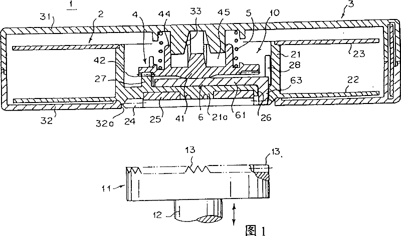
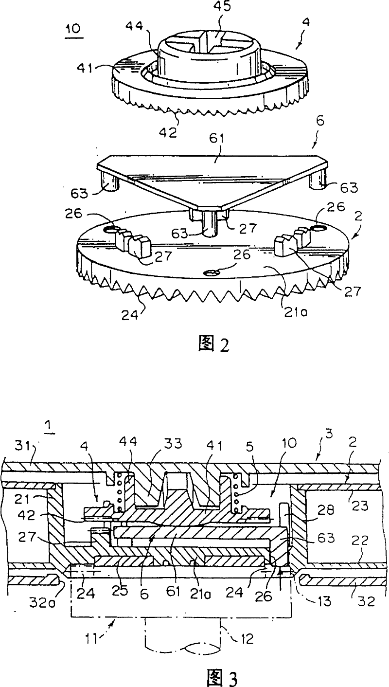
[0050] Embodiment 1 of the present invention for achieving the first object will be described in detail below with reference to the drawings. Fig. 1 is the cross-sectional front view of the tape cassette with the tape control reel of Embodiment 1 of the present invention in the non-use state; Fig. 2 is an exploded perspective view showing the main parts of the tape cassette in Fig. 1; Fig. 3 is a view showing that the tape cassette in Fig. 1 is in use Sectional view of the main parts in the state.

[0051] The structure of the tape cassette 1 is: a tape (not shown) is wound on a single tape control reel 2, and a tape cassette case in which an upper case 31 and a lower case 32 having an opening 32a in the center are connected and fixed by means of small screws or the like. 3, the tape control reel 2 is accommodated and enabled to rotate.

[0052] The tape control reel 2 includes: a bottomed cylindrical tape control reel center 21 on which a magnetic tape is wound on the outer ...

Embodiment 2

[0068] Embodiment 2 and Embodiment 3 of the present invention for achieving the second object will be described in detail below with reference to the drawings.

[0069] Fig. 6 is the sectional view of the tape control reel of the magnetic tape cassette according to Embodiment 2 of the present invention;

[0070] Fig. 7 is an enlarged view of main parts of Fig. 6 .

[0071] The tape control reel 101 is a cylindrical hub 103 on which a magnetic tape is wound on an outer peripheral surface 103a by using synthetic resin, and a disc-like extension extending radially from the outer circumference of the hub 103 side end (lower in the figure). The formed flange portion 104 is integrally formed, and a disc-shaped flange 105 molded separately from synthetic resin is fixed to the other end portion of the hub 103 with an adhesive.

[0072] The disk-shaped inner wall 111 is connected to the inner peripheral side of the hub 103, and the outer surface of the inner wall 111 is annularly prov...

Embodiment 3

[0088] And, in the present embodiment 3, also can according to need, the bonding part between the recessed part end surface 109a of the hub 103 and the inner peripheral side flange face 105a of the flange 105 and / or the recessed part peripheral surface of the hub 103 At least one of the two bonding surfaces of the bonding portion between the bonding portion 109b and the inner peripheral end surface 105b of the flange 105 is roughened, thereby improving the bonding strength with the adhesive.

[0089] Same as the previous example, according to the present embodiment 3, by using an adhesive to combine the hub 103 and the flange 105, the flange 105 can not be deformed, and the whole circumference can be evenly bonded, and the flange 105 The rotation vibration is small, and the variation in the width direction is also relatively small when the tape is running, so it can meet the requirements of high density.

[0090] Moreover, by bonding the hub 103 and the flange 105 with two ver...


PUM


Abstract

A reel (2) of a magnetic tape cartridge (1) which is rotatably housed in a cartridge case (3) and on which a magnetic tape is wound, wherein a magnet attracting in a reel bottom wall (21a), where the centre hole (25a) a metal plate (25) is integrally insert-molded on the bottom face, the metal plate (25) is formed into an annular shape having a center hole (25a), and, at the insert-molding time, a resin is injected from the gate at the center portion of the center hole (25a) of the metal plate (25) to form a recess (21b) of the metal plate (25) is sealed with the resin, at a portion between the gate trace (21c) of the center portion and the inner circumference of the center hole (25a) of the metal plate (25).

Description

[0001] This application is a divisional application, the application number of its parent application is: 99813260.8, the application date: 1999.11.11, the invention name: tape cassette control tape reel. technical field [0002] The invention relates to a magnetic tape cassette control reel in which a single control reel on which a magnetic tape is wound is accommodated in a magnetic tape cassette shell and rotatable. Background technique [0003] Conventionally, in a magnetic tape cassette used as a storage medium for an external storage device such as a computer, it has been known to wind a magnetic tape on a single control reel, then house the control reel in a cassette case and use it The type that can rotate. This tape is used to store data on a computer, etc. Since it contains important information, it is necessary to prevent the tape from jamming and other failures, and to prevent the tape from being accidentally pulled out when it is not in use, such as for storage....

Claims


Application Information

Patent Timeline
Patent Type & Authority Patents(China)
IPC IPC(8): G11B23/107G11B23/113G11B15/66G11B23/037G11B23/04G11B23/087
CPCG11B23/043G11B15/662G11B23/044G11B23/107G11B23/037G11B23/08728G11B23/087
Inventor 志贺英昭露木诚治
Owner FUJIFILM CORP
Why Eureka
Try Eureka