
Internal combustion engine

A technology for internal combustion engines and engines, applied to internal combustion piston engines, combustion engines, mechanical equipment, etc., can solve problems such as unfavorable layout and utilization of structural space, and achieve the effects of improving exhaust quality, increasing power, and good noise reduction

Inactive Publication Date: 2007-11-28
ANDREAS STIHL AG & CO KG
View PDF4 Cites 0 Cited by
  • Summary
  • Abstract
  • Description
  • Claims
  • Application Information

AI Technical Summary

Problems solved by technology

This leads to an unfavorable arrangement, with which it is not possible to make good use of the existing construction space

Method used


Image

  • Internal combustion engine
  • Internal combustion engine

Examples


Embodiment Construction

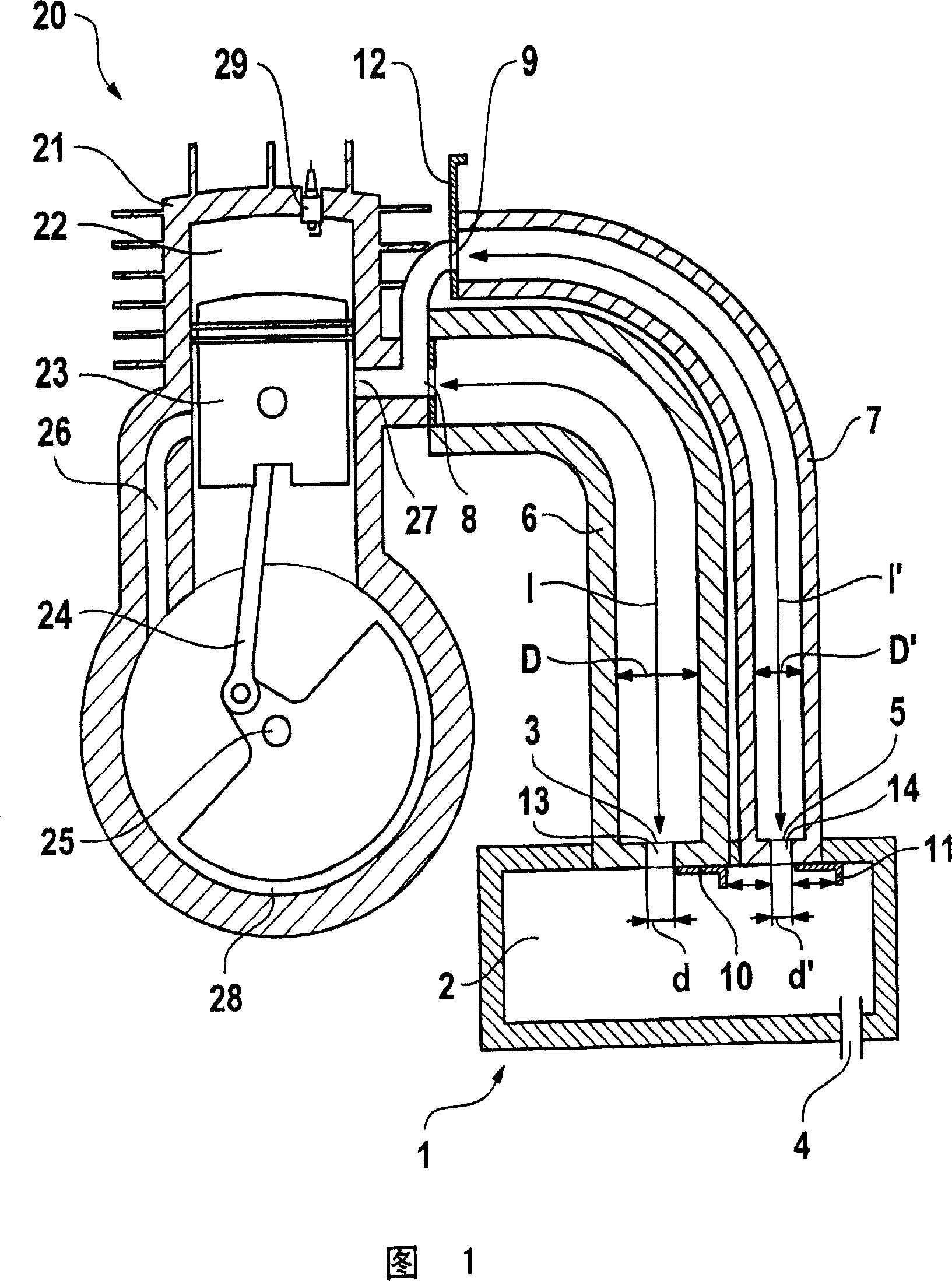
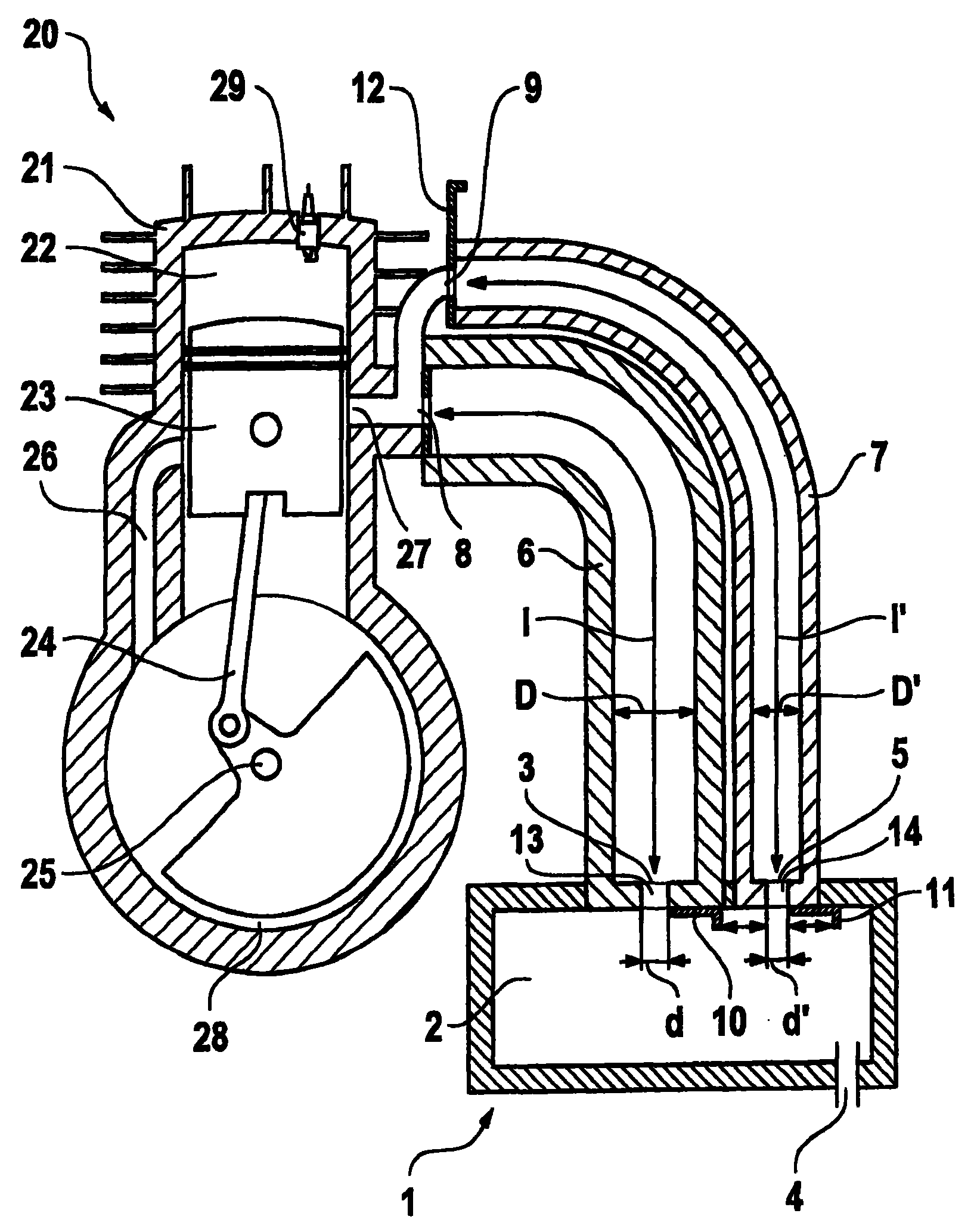
[0009] The internal combustion engine 20 is designed as a two-stroke engine and has two cylinders 21 in which a combustion chamber 22 is arranged. The combustion chamber 22 is delimited by a reciprocating piston 23 , which drives a crankshaft 25 rotatably mounted in a crankcase 28 via a connecting rod 24 . The crankcase 28 is connected to the combustion chamber 22 at a predetermined position of the piston 23 via at least one overflow pipe 26 .

[0010] During operation of the internal combustion engine 20 , the fuel / air mixture is supplied to the crankcase 28 via an inlet (not shown). As the piston 23 moves downward, the mixture is compressed in the crankcase 28 and flows into the combustion chamber 22 through one or more overflow tubes 26 at the bottom dead center of the piston 23 . The mixture is compressed in the combustion chamber 22 by the upwardly moving piston 23 and ignited by the spark plug 29 at the top dead center. Exhaust gases flow out of the combustion chamber ...


PUM


Abstract

An internal combustion engine, especially of a two-stroke engine in a portable handheld work apparatus, includes an outlet (27) for the exhaust gases which is fluidly connected with at least one inlet opening (13, 14) in an exhaust-gas muffler (1). At least one resonance pipe (6, 7) is mounted in flow direction between the outlet (27) from the engine (20) and the inlet opening (3, 5) into the exhaust-gas muffler (1) in order to obtain a good noise attenuating result and simultaneously make possible an advantageous, space-saving mounting of the engine (20).

Description

technical field [0001] The present invention relates to an internal combustion engine, in particular a two-stroke engine in a hand-operated portable implement, such as a motorized chainsaw, cutting machine, etc., which has at least one inlet opening for the exhaust gases and in the exhaust muffler An outlet for fluid communication. Background technique [0002] An internal combustion engine is known from WO 01 / 21941 A1, the outlet of which opens into the sound absorbing chamber of a sound absorber. A closed resonance tube is arranged between the outlet and the exhaust muffler. In order to effectively eliminate noise, the resonant tube must have a relatively large length. This results in a disadvantageous arrangement, with which it is not possible to make good use of the available installation space. Contents of the invention [0003] The object of the present invention is to provide an internal combustion engine of the above-mentioned type which has good sound attenuati...

Claims


Application Information

Patent Timeline
Patent Type & Authority Patents(China)
IPC IPC(8): F01N1/02F02B63/02F01N1/08F01N13/00F02B27/06F02B75/02
CPCF02B2075/025F01N13/002F01N1/02Y02T10/146F01N2590/06F01N1/08F02B27/06Y02T10/12
Inventor A·克利梅克T·塞德尔
Owner ANDREAS STIHL AG & CO KG
Learn More