Continuous radial loader for steam turbine reaction blade and its method

A technology for turbine blades and blades, applied in gas turbine devices, blade support elements, jet propulsion devices, etc., can solve problems such as blade and rotor damage

Inactive Publication Date: 2007-11-28
GENERAL ELECTRIC CO
View PDF8 Cites 0 Cited by
  • Summary
  • Abstract
  • Description
  • Claims
  • Application Information

AI Technical Summary

Problems solved by technology

However, these thumping operations can cause damage to the blades and rotor

Method used


Image

  • Continuous radial loader for steam turbine reaction blade and its method
  • Continuous radial loader for steam turbine reaction blade and its method
  • Continuous radial loader for steam turbine reaction blade and its method

Examples


Embodiment Construction

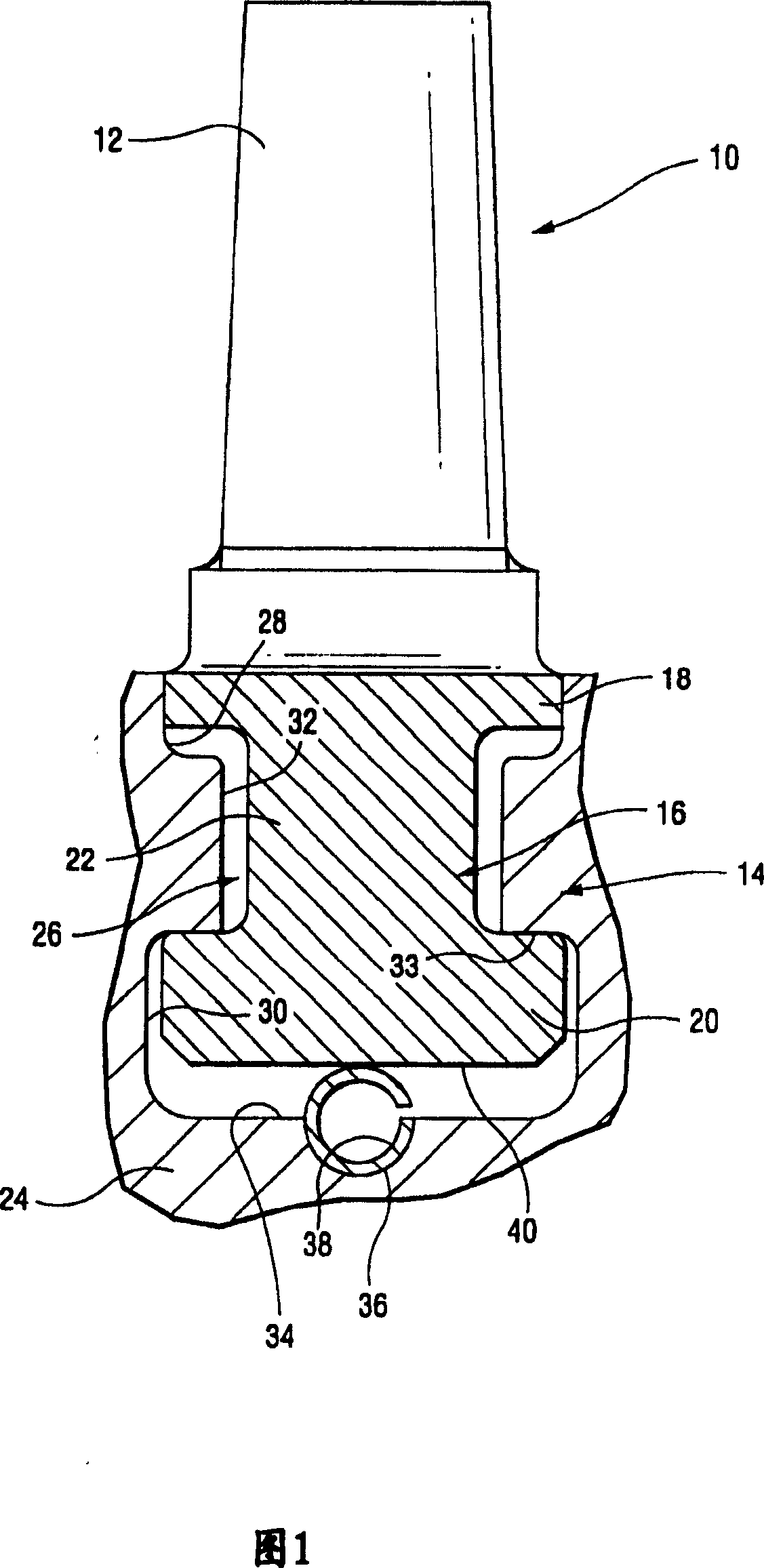
[0014] Referring to FIG. 1 , a turbine blade 10 includes an airfoil portion 12 and a root or base portion 14 configured as a male dovetail portion 16 . The male dovetail portion includes radially outer protrusions or hooks 18 and inner protrusions or hooks 20 spaced radially by a narrow neck 22 .

[0015] The rotor 24 is provided with an annular retaining slot configured as a female dovetail slot 26 around the periphery of the wheel and has a radially outer wide slot portion 28, a radially inner wide slot portion 30 and a The middle narrow groove portion 32, the radially outer wide groove portion 28 is used to receive the outer male protrusion 18, the radially inner wide groove portion 30 is used to receive the inner male protrusion 20, and the middle narrow groove portion 32 is used to receive the narrow neck 22 . The bottom surface 33 of the slotted portion 32 forms a so-called “hook” which engages with the inner protrusion 20 on the male dovetail portion 16 . In the base ...


PUM


Abstract

A loading spring segment for radially loading a turbine bucket within a turbine rotor groove includes a substantially circular metal sheet with a gap between opposed edges of the sheet, the sheet defining an arcuate segment in an arcuate length direction of the spring segment; and a plurality of radial slots in the sheet, spaced along the arcuate length direction to thereby create a plurality of individual springs within the arcuate segment.

Description

technical field [0001] This invention relates to the art of steam turbine blades, and more particularly, to a radially loaded spring for use in mounting steam turbine reaction blades into steam turbine rotor slots. Background technique [0002] The current practice of radially mounting steam turbine reaction blades involves inserting each blade into a retention slot in the steam turbine rotor, inserting a load pin into a tight space between the bottom of the blade and the rotor slot. The pin is then hammered within a tightly controlled radial clearance, causing it to deform in the radial direction of the rotor so that the blade radially rests against a hook in the retention slot. For each blade, there is a load pin and each load pin must be hammered manually until the blade does not move within the rotor slot. However, these thumping operations can cause damage to the blades and rotor. Therefore, there is a need for an improved radial loading technique that can reduce part...

Claims


Application Information

Patent Timeline
Patent Type & Authority Patents(China)
IPC IPC(8): F01D5/30F01D5/28F02C7/00
CPCF01D5/3038F01D5/30
Inventor 戴维·O·菲茨罗纳德·W·科曾约翰·T·墨菲
Owner GENERAL ELECTRIC CO
Why Eureka
Try Eureka