
Biconditional transmission monitoring alarm and telemechanical control industrial television camera with integrative steel structure

An industrial TV and camera technology, which is applied to TV, color TV, color TV parts, etc., can solve the problems of complex overall structure and servo drive system, inconvenient disassembly and maintenance, and many production links, so as to achieve enhanced operation. Ability and anti-interference, easy production and maintenance, exquisite modeling effect

Inactive Publication Date: 2007-11-07
孟令彪
View PDF6 Cites 0 Cited by
  • Summary
  • Abstract
  • Description
  • Claims
  • Application Information

AI Technical Summary

Problems solved by technology

[0003] 1. The overall structure and servo drive system of the product are complex, with many production links, high cost investment, single function, and inconvenient disassembly and maintenance
[0004] 2. The product cannot meet the high-level needs of customers. For example, the integrated function of infrared alarm, remote control and camera cannot be completed at the same time for the active target product based on the same location; in the case of complex geographical environment and installation conditions, the product cannot To meet the needs of customers, the image signal and control signal can not only realize wireless transmission, but also complete wired transmission and the function of mutual conversion transmission mode as required
[0005] 3. There are different degrees of defects in the appearance of the product, the selection of materials and the improvement of the product's anti-interference, anti-dust and uninterrupted operation capabilities under complex climate conditions
[0006] 4. The product lacks adaptability to high-end installation environment and beauty decoration environment

Method used


Image

  • Biconditional transmission monitoring alarm and telemechanical control industrial television camera with integrative steel structure
  • Biconditional transmission monitoring alarm and telemechanical control industrial television camera with integrative steel structure
  • Biconditional transmission monitoring alarm and telemechanical control industrial television camera with integrative steel structure

Examples


Embodiment Construction

[0018] The present invention will be described in detail below in conjunction with the embodiments and with reference to the accompanying drawings.

[0019] Whole mechanical structure and working principle of the present invention

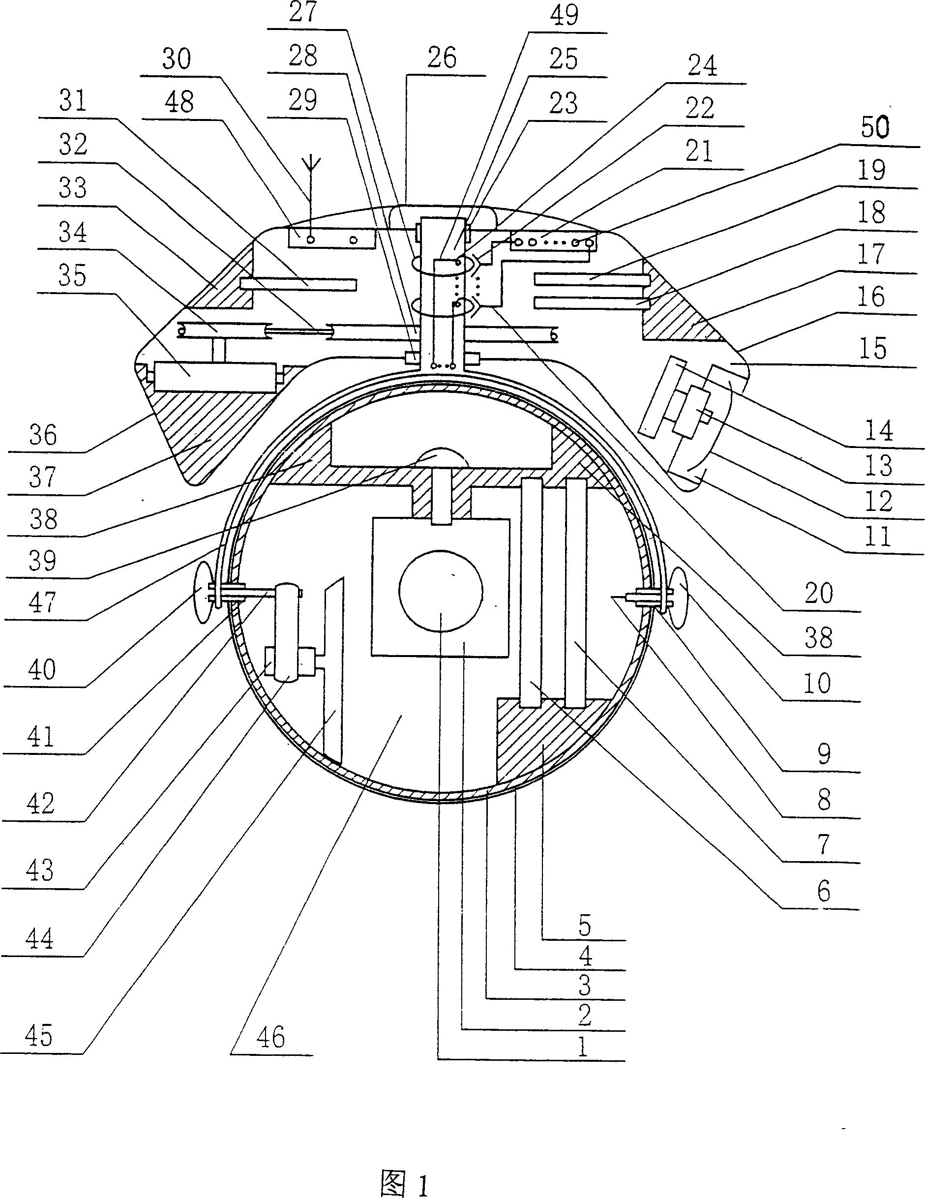
[0020] The dome camera core 2 shown in Fig. 1 realizes the camera function through the camera lens window 1, and the window is equipped with an arc-shaped spherical optical glass sheet, which is a pixel acquisition port for photoelectric conversion between the camera core and the outside world. The main sphere shell 4 is a steel spherical shell, which is divided into a front hemispherical shell and a rear hemispherical shell. Camera core hanger 38, it fixes camera core 2 on the vertical line of sphere middle ring by camera core center fixing screw 39. The lower right of the inner side of the main sphere ring 3 is the main sphere module fixing slot 5, which can insert and fix the image radio frequency circuit module 7 and the two-state digital cont...

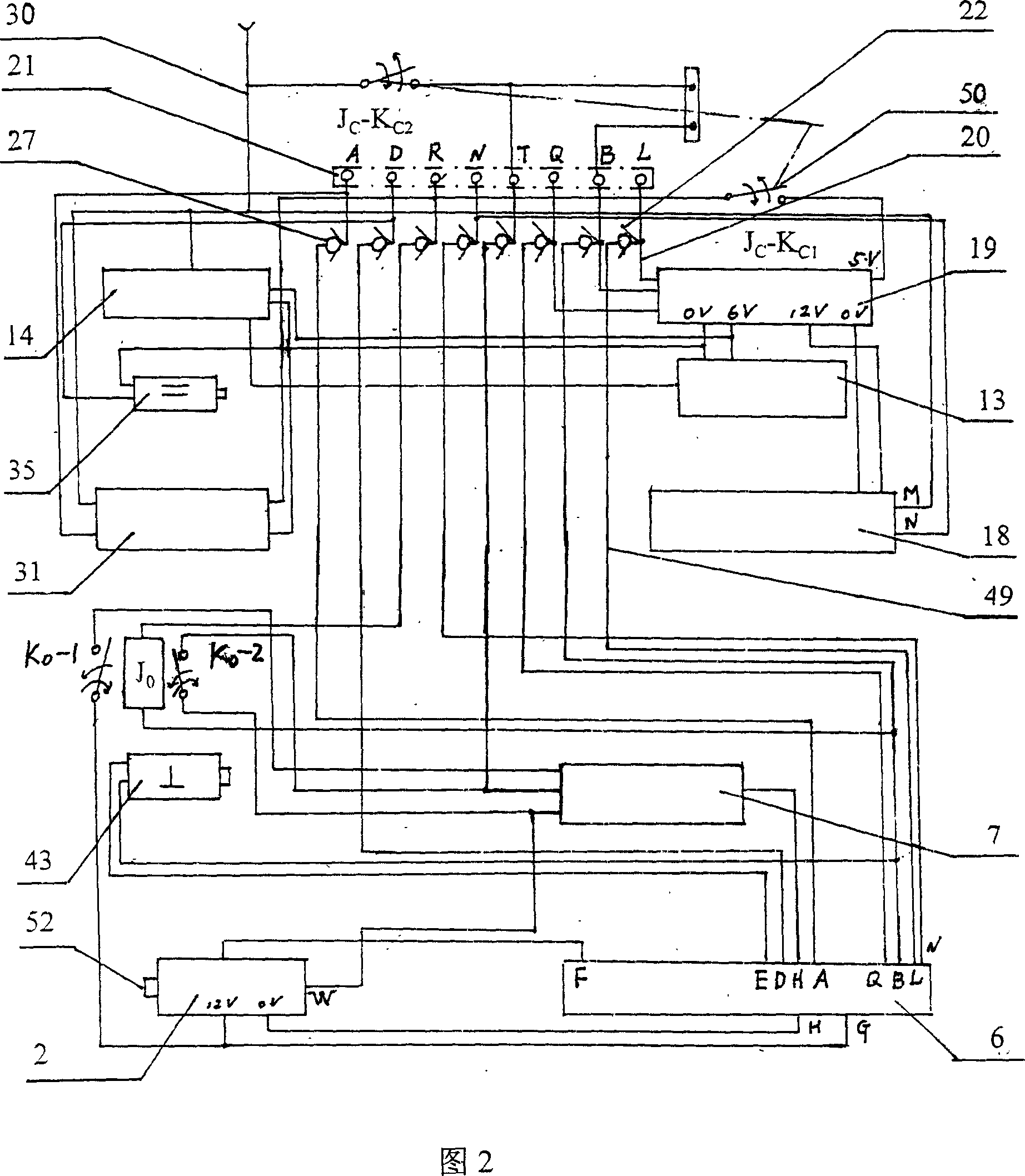
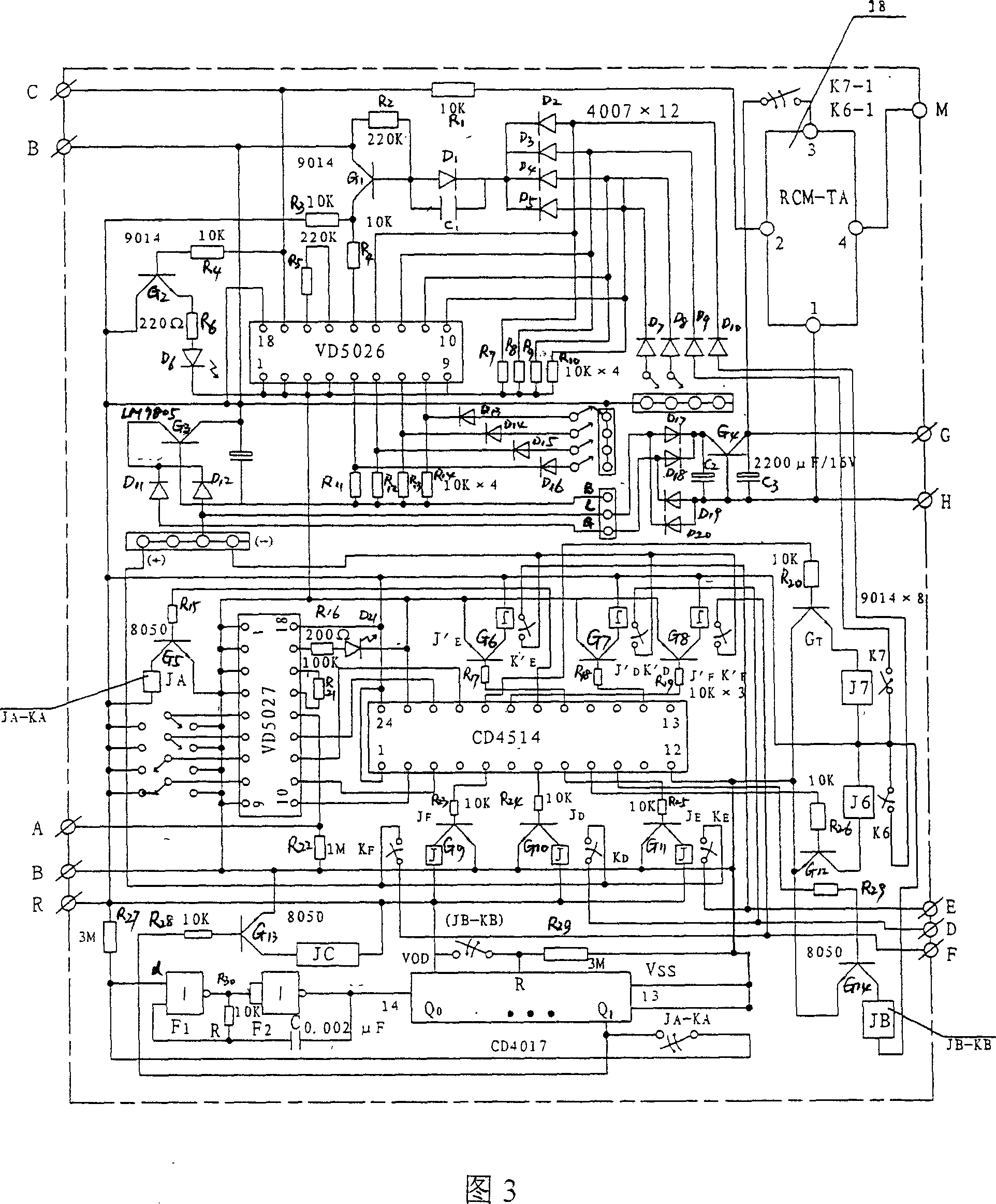

PUM


Abstract

This invention relate to an industry television cameral, which in detail is an industry television ball cameral integrated with visual picture and infrared alarming and remote moving control. It is characterized by the following: the cameral core is located in the perpendicular bisector of the main ball middle ring and together with its pitching rotation structure is located inside the main ball; there are located with the plug rolling connection by the middle ring right axis cover and left axis cover and right middle axis and left middle axis at the crossing point where the main ball middle ring both sides crosses along their diameter direction, wherein, its upper part is an electricity output brush formed by the conductive ring column in the center of the level box and conductive inner ring and outer ring; and its down part are the middle ring left axis hung outside the main ball and the conductive ring bridge rack of the semi-round arc.

Description

technical field [0001] The invention relates to an industrial television camera, in particular to a steel structure industrial television spherical camera which integrates functions of video image, infrared alarm and remote control, and also has wireless and wired dual-state transmission monitoring and alarm. Background technique [0002] The applicant has successively applied for two utility model patents of "lamp-type hidden industrial TV camera" and "hidden smart industrial TV camera", the patent numbers of which are: 93228396.9 and 98236829.1 respectively. From the perspective of facilitating production requirements, reducing production costs and adapting to user requirements for product functions, both of the above two patents have the following deficiencies: [0003] 1. The overall structure and servo drive system of the product are complex, with many production links, high cost investment, single function, and inconvenient disassembly and maintenance. [0004] 2. The...

Claims


Application Information

Patent Timeline
Patent Type & Authority Patents(China)
IPC IPC(8): G03B19/00H04N5/225
Inventor 孟令彪吴同林
Owner 孟令彪
Learn More