Deep-water submersible biorobot of cuttlefish imitation type mollush
A technology of bionic robots and molluscs, applied to water toys, water toys, toys, etc., can solve problems such as large volume, complex overall structure, and mechanical failure of the transmission device
- Summary
- Abstract
- Description
- Claims
- Application Information
AI Technical Summary
Problems solved by technology
Method used
Image

Examples
specific Embodiment approach 1
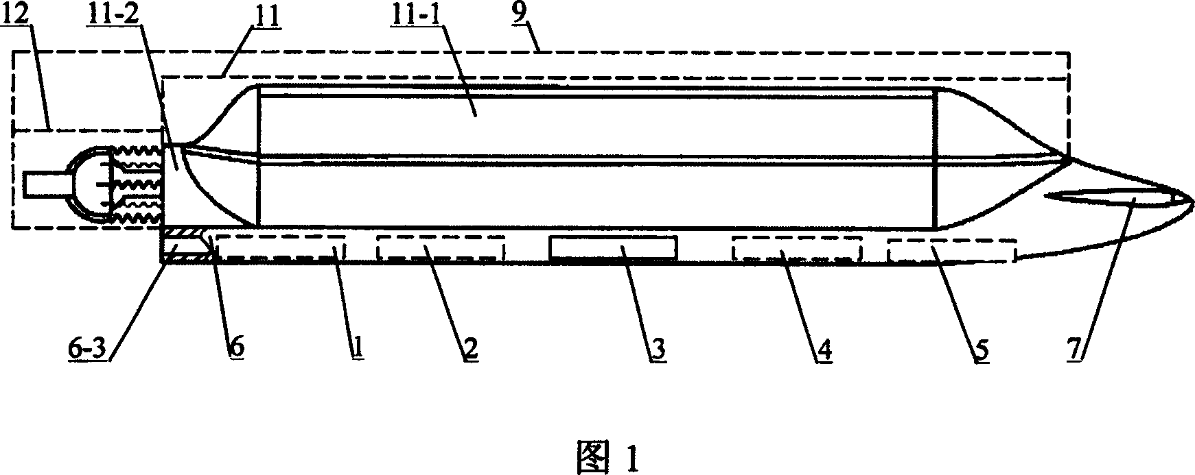
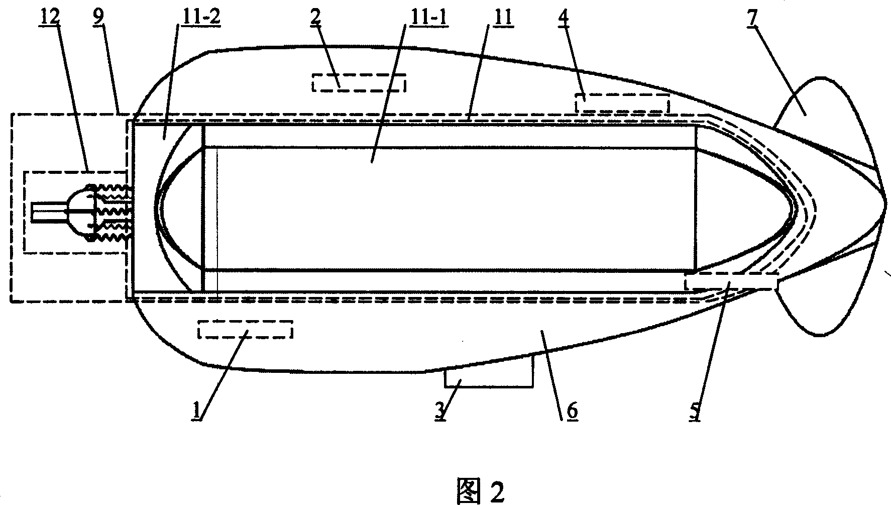
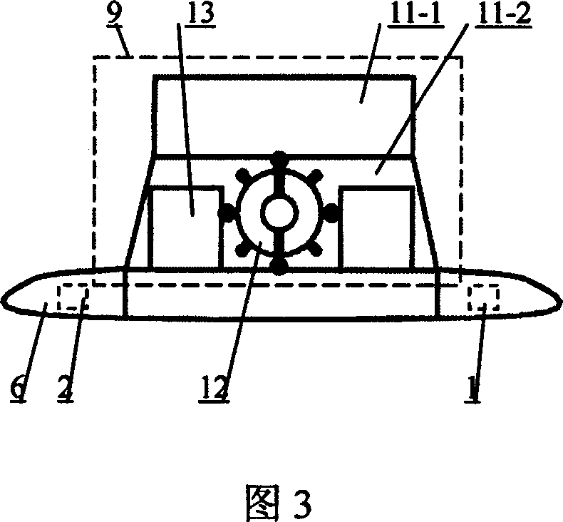
[0006] Specific Embodiment 1: This embodiment is described in conjunction with Fig. 1, Fig. 2 and Fig. 3. This embodiment consists of a battery 1, a control computer 2, a sinking control device 3, a motion control circuit 4, a communication device 5, a substrate 6, and a single pulse propulsion A device 9 and a fin controller 7; a battery 1, a control computer 2, a motion control circuit 4, and a communication device 5 are respectively fixed in the cavity 6-3 of the base body 6; A monopulse propeller 9 is fixed on the upper end surface of the monopulse propeller 9, and a fin controller 7 is fixed on the substrate 1 at the right end of the monopulse propeller 9.
specific Embodiment approach 2
[0007]Specific embodiment two: This embodiment is described in conjunction with Fig. 4, Fig. 5, and Fig. 6. The monopulse thruster 9 of this embodiment is composed of a cavity 11, a nozzle assembly 12, a cavity shape memory alloy driver 17, and a cavity return spring 18. The water inlet device is composed of; the cavity 11 is composed of a skin cavity 11-1 and a chamber 11-2; The top plate 11-1-1, the bottom plate 11-1-2, and the skin 11-1-3 are composed; the bottom plate 11-1-2 and the top plate 11-1-1 are fixedly connected through the skin 11-1-3 to form a cover The leather cavity 11-1, the bottom plate 11-1-2 is fixedly connected with the base 6, and a set of cavity shape memory alloy drivers 17 and a set of cavity return springs are connected between the top plate 11-1-1 and the bottom plate 11-1-2 18. A water inlet device is provided on the cavity 11, and the left end of the cavity 11 is fixedly connected with the nozzle assembly 12. The top plate 11-1-1 is made of low-d...
specific Embodiment approach 3
[0008] Specific embodiment three: This embodiment is described in conjunction with Fig. 8, Fig. 9, and Fig. 10. The nozzle assembly 12 of this embodiment consists of a nozzle 12-1, a shape memory alloy driver 12-2 for controlling the rotation of the nozzle, and a nozzle return spring 12- 3. The nozzle pipe support 12-4, the first connection frame 12-5, the second connection frame 12-6, the third connection frame 12-7, and the fourth connection frame 12-8; the right end of the nozzle pipe support 12-4 Fixedly installed in the through hole of the left end face 11-2-3 of the chamber 11-2, the spherical surface 12-4-1 of the left end of the nozzle pipe support 12-4 is contained in the spherical cavity 12-1-1 of the nozzle 12-1 Inside and hinged with the nozzle 12-1, the spherical outer surface 12-1-2 of the nozzle 12-1 is symmetrically fixed with a group of first connecting frames 12-5 and a group of second connecting frames 12-6 along the circumferential direction, which are conne...
PUM
 Abstract
Description
Claims
Application Information
 - Generate Ideas
- Intellectual Property
- Life Sciences
- Materials
- Tech Scout
- Unparalleled Data Quality
- Higher Quality Content
- 60% Fewer Hallucinations
Browse by: Latest US Patents, China's latest patents, Technical Efficacy Thesaurus, Application Domain, Technology Topic, Popular Technical Reports.
© 2025 PatSnap. All rights reserved.Legal|Privacy policy|Modern Slavery Act Transparency Statement|Sitemap|About US| Contact US: help@patsnap.com