


Quick Research
Generate reliable direction feasibility study reports for your R&D in just a few steps.

Technical Q&A
Discover and master advanced knowledge NOW. Basics, ideas, possibilities, all at once.

Find Solutions
As an expert in R&D theories, this can generate solutions to your technical problems instantly.

Evaluate Feasibility
Analyze your overall solution with one click, know your potential R&D risks in advance.

Monitor Landscape
Get weekly tech updates, stay abreast of the latest tech innovations and key insights.
Transmitting bar code reader
A card-reading device and card-reading technology, applied in the direction of electromagnetic radiation induction, etc., can solve the problems of high sampling frequency, low card-reading efficiency, and high cost of laser scanners, and achieve slow card-reading speed, reduced equipment cost, and long life Effect
- Summary
- Abstract
- Description
- Claims
- Application Information
AI Technical Summary
Problems solved by technology
Method used
Image

Examples
Embodiment Construction
[0013] The present invention will be described in detail below in conjunction with the accompanying drawings and specific embodiments.
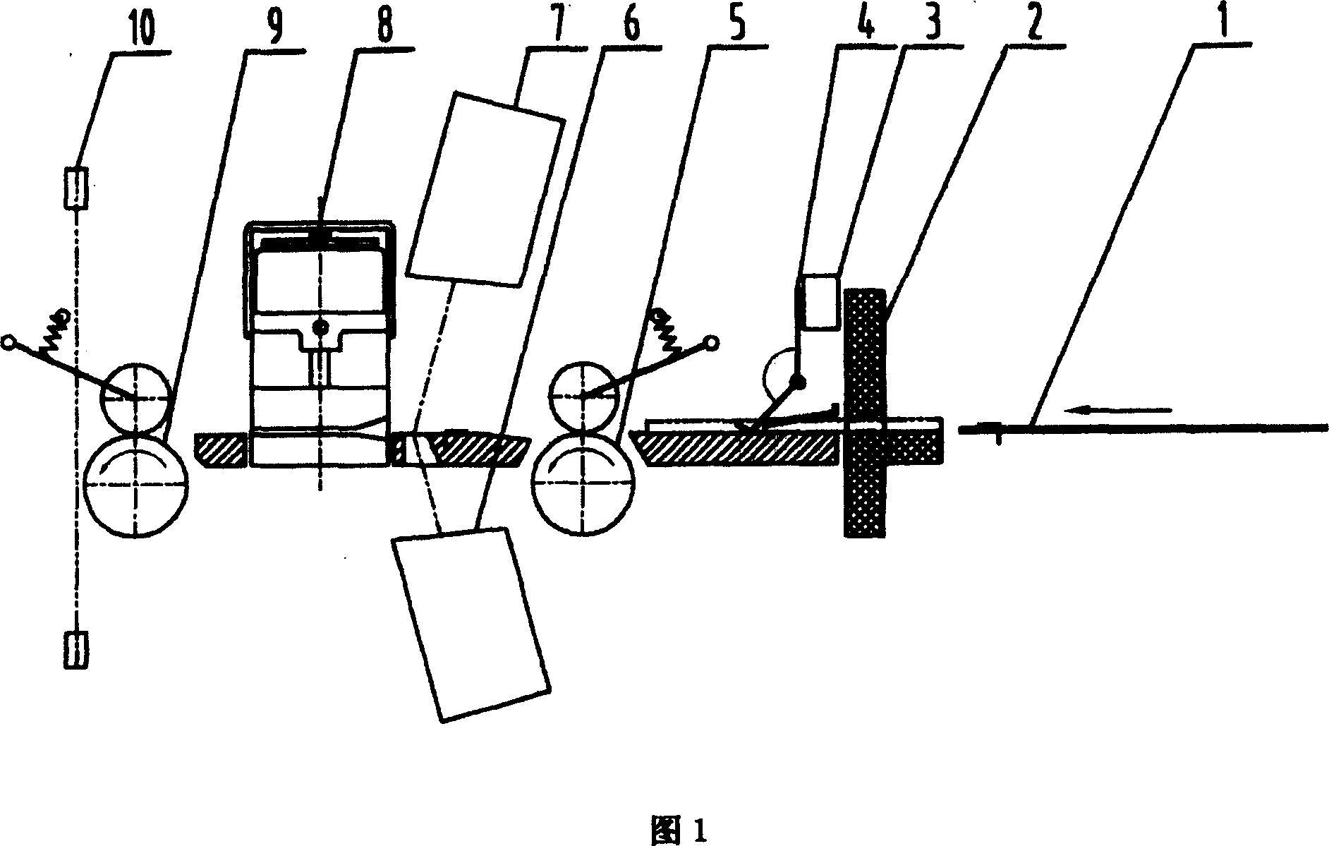
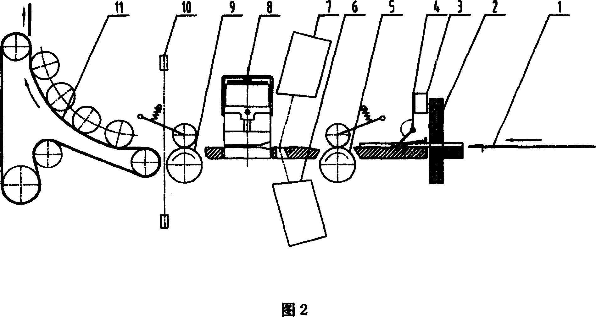
[0014] As shown in Figure 1, when the barcode card 1 is inserted from the voting port 2, the flip door 4 is pushed to turn over, and the micro switch 3 connected to it is driven to generate an electrical signal, the stepping motor and the scanner 6, 7 are started, and the stepping The motor drives two pairs of rubber wheels 5 and 9 to rotate, and transmits the front end of the barcode card 1 between the scanners 6 and 7, and the upper and lower CCD scanners scan the front end of the barcode card 1, and the stepping motor adopts slow speed during scanning. The speed of the transmission is advanced to adapt to the low scanning frequency of the CCD scanner. If the barcode is just at the front end, the card will be read successfully; Scan between the scanners 6 and 7 to read the barcode. The barcode card 1 continues to move forward under the dri...
PUM
 Abstract
Description
Claims
Application Information
 - R&D Engineer
- R&D Manager
- IP Professional
- Industry Leading Data Capabilities
- Powerful AI technology
- Patent DNA Extraction
Browse by: Latest US Patents, China's latest patents, Technical Efficacy Thesaurus, Application Domain, Technology Topic, Popular Technical Reports.
© 2024 PatSnap. All rights reserved.Legal|Privacy policy|Modern Slavery Act Transparency Statement|Sitemap|About US| Contact US: help@patsnap.com