Internal expanding type electromagnetic brake

An electromagnetic brake, internal tensioning technology, applied to drum brakes, brake types, brake components, etc., can solve problems such as large structure size, easy wear of guide shafts, and electromagnetic attraction of brakes.

Inactive Publication Date: 2007-10-17
SHANGHAI MITSUBISHI ELEVATOR CO LTD
View PDF6 Cites 0 Cited by
  • Summary
  • Abstract
  • Description
  • Claims
  • Application Information

AI Technical Summary

Problems solved by technology

The spring force is located at the upper and lower ends of the brake arm. The spring force produces a large bending moment on the brake arm. At the same time, the braking friction also produces a large bending moment on the two guide shafts of the brake arm. Therefore, the brake arm The structure size is also relatively large, occupying a large effective space inside the braking surface, and the guide shaft is easy to wear
Since the guide shaft of the brake arm is far away from the center of the brake, when the brake is in the braking state, the different rotation tendencies of the braking surface will cause a large change in the upper and lower air gaps between the movable armature and the fixed iron core , which has a greater impact on the electromagnetic attraction of the brake

Method used


Image

  • Internal expanding type electromagnetic brake
  • Internal expanding type electromagnetic brake
  • Internal expanding type electromagnetic brake

Examples


Embodiment Construction

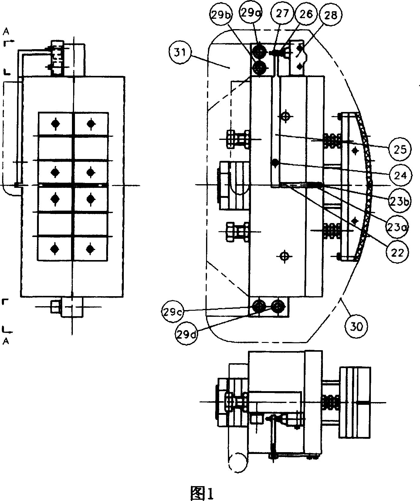
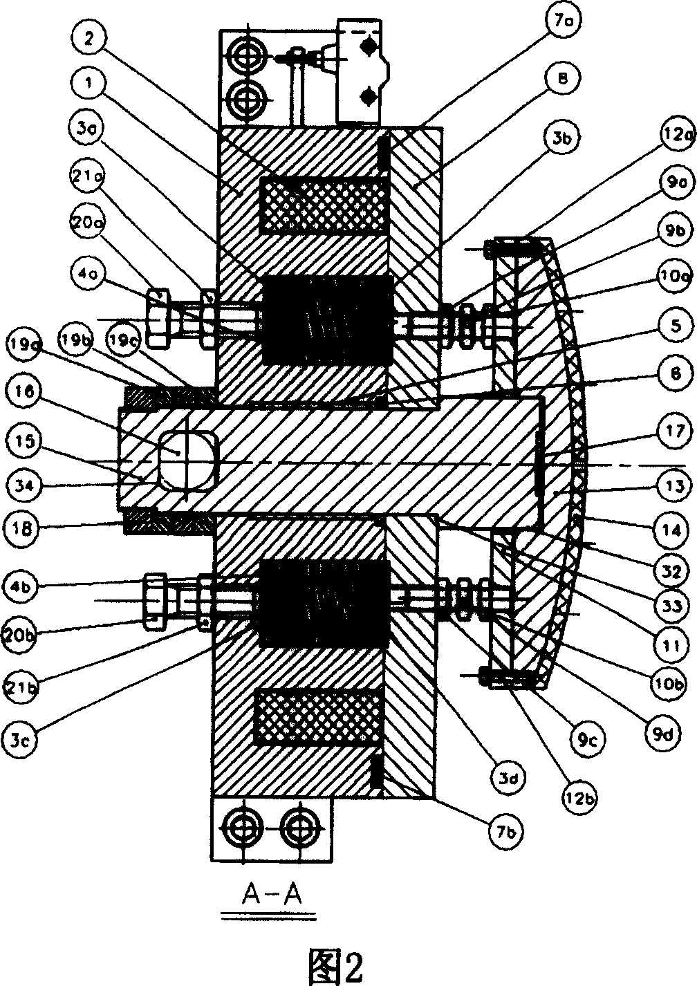
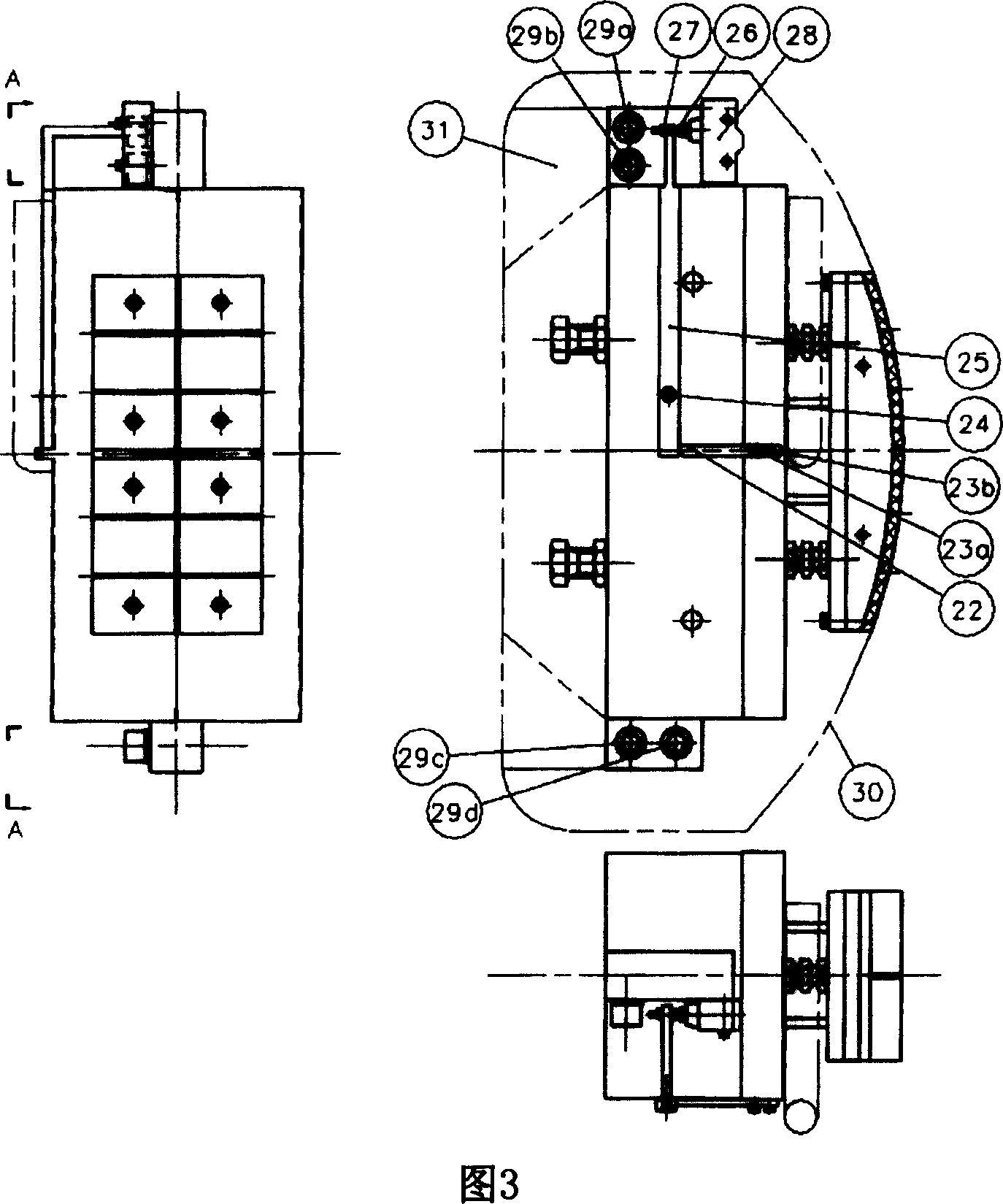
[0015] As shown in FIGS. 1 and 2 , the first embodiment of the internal tension electromagnetic brake of the present invention includes a fixed core 1 , a movable armature 8 , a coil 2 , brake shoes 13 , friction plates 14 , and a compression spring 4 .

[0016] It also includes a main shaft 15 which is arranged in the hole at the middle position of the fixed iron core 1 through the sliding bearing 5 and the bushing 6 . The sliding bearing 5 is a lubrication-free bearing, so the lubrication of the main shaft 15 need not be considered. The function of the shaft sleeve 6 is to prevent the sliding bearing 5 from being taken out of the fixed iron core 1. Therefore, the shaft sleeve 6 is installed on the side of the sliding bearing 5 in the hole of the fixed iron core 1. The shaft sleeve 6 and the hole of the fixed iron core 1 are tight. Cooperate.

[0017] The brake shoe 13 is provided with a rectangular opening 32 (see FIG. 5 ), through which the main shaft 15 passes through the...


PUM


Abstract

An electromagnetic brake of internal expansion type is prepared as embedding the whole brake in brake drum and laying it symmetrically to axis of brake drum, setting a main-shaft at fixed iron core of brake, passing main-shaft through active armature and extending it into braking slipper for using main-shaft to bear torque generated by braking-frictional force.

Description

technical field [0001] The invention relates to an internal tension electromagnetic brake for a permanent magnet synchronous gearless traction machine. Background technique [0002] Most of the original electromagnetic brakes are disc and drum brakes. The main braking surface of the disc brake is the two sides of the brake disc, while the braking surface of the drum brake is the outer peripheral surface of the brake drum. The brakes of these two structures often require a large space in the radial direction, especially in the axial direction. Therefore, miniaturization cannot be achieved within the designed space. Moreover, the action sound of the brake is relatively loud, the structure is complex, and there are difficulties in assembly and debugging. It is often very difficult to obtain the required electromagnetic force in a limited space. [0003] The internal tension electromagnetic brake can solve the shortcomings of disc and drum brakes. The whole brake is arranged...

Claims


Application Information

Patent Timeline
Patent Type & Authority Patents(China)
IPC IPC(8): F16D65/21F16D51/18F16D65/18
Inventor 周双林王兴琪甘靖戈王水来方凯
Owner SHANGHAI MITSUBISHI ELEVATOR CO LTD
Why Eureka
Try Eureka