Tie back snap

a safety hook and back snap technology, applied in the direction of eye fasteners, hook fasteners, fastening means, etc., can solve the problems of double action, single locking snaps that cannot work for this type of application, and the actual fall path and restraint conditions are rather unpredictable, so as to reduce the applied gate load, prevent rollout (accidental disengagement), and light weight

Inactive Publication Date: 2013-03-19
RELIANCE INDUSTRIES LIMITED
View PDF15 Cites 0 Cited by
  • Summary
  • Abstract
  • Description
  • Claims
  • Application Information

AI Technical Summary

Benefits of technology

[0018]The present invention relates to an improved method of constructing a tie back snap for fall arrest applications that can be produced using existing manufacturing technology, so can be made light weight, can be produced with a stamped steel gate, can be produced so that it can be snapped directly to its' own. lanyard webbing without the possibility of the webbing being able to slip behind the gate to cause failure under load and can be produced at a cost no higher than existing standard locking snap hooks.
[0019]The present invention relates to a new and unique method of designing a locking anchorage snap so that it can be tied (or snapped) back onto its own lanyard in a manner that will not damage or cut the lanyard nor cause damage to the snap itself. Additionally, this patent relates to a method to lock and unlock the snap gate so that it reduces the applied gate loads. Additionally, this patent relates to a new and unique method of designing a snap gate so that it is impossible for the lanyard to apply outward forces to the tie back snap gate when the snap is connected back to its own lanyard. Additionally, this patent applies to a method used to prevent rollout (accidental disengagement) of the locking snap.
[0027]g. A flat widened portion of the forged snap hook body to relieve and distribute tension in the webbing during fall arrest.
[0029]l. A method to soften the edge of the snap to prevent damage to the webbing while moving through the snap.

Problems solved by technology

Because of the variety of attachment points and work condition present during an instance where the safety hook and fall arrest systems must be deployed, the actual fall path and restrain conditions are rather unpredictable.
In the second application the lanyard is looped over the pipe or beam and then the snap is connected or snapped back around the lanyard itself This type of application has several inherent problems.
The first problem is that the lanyard webbing can lie across the inside of the snap gate.
Therefore standard, double action, single locking snaps will not work for this type of application.
Another danger with the use of snap hooks is that a snap, when looped over an I-beam with the edge of the gate against the flange of the I-beam, can fail by forces on the gate which can open by the due to the action of the I-beam pressing against the gate during fall arrest.
All of which adds greatly to the cost and weight of the product.

Method used


Image

  • Tie back snap
  • Tie back snap
  • Tie back snap

Examples


Embodiment Construction

[0040]While the invention will be described and disclosed here in connection with certain preferred embodiments, the description is not intended to limit the invention to the specific embodiments shown and described here, but rather the invention is intended to cover all alternative embodiments and modifications that fall within the spirit,and scope of the invention as defined by the claims included herein as well as any equivalents of the disclosed and claimed invention.

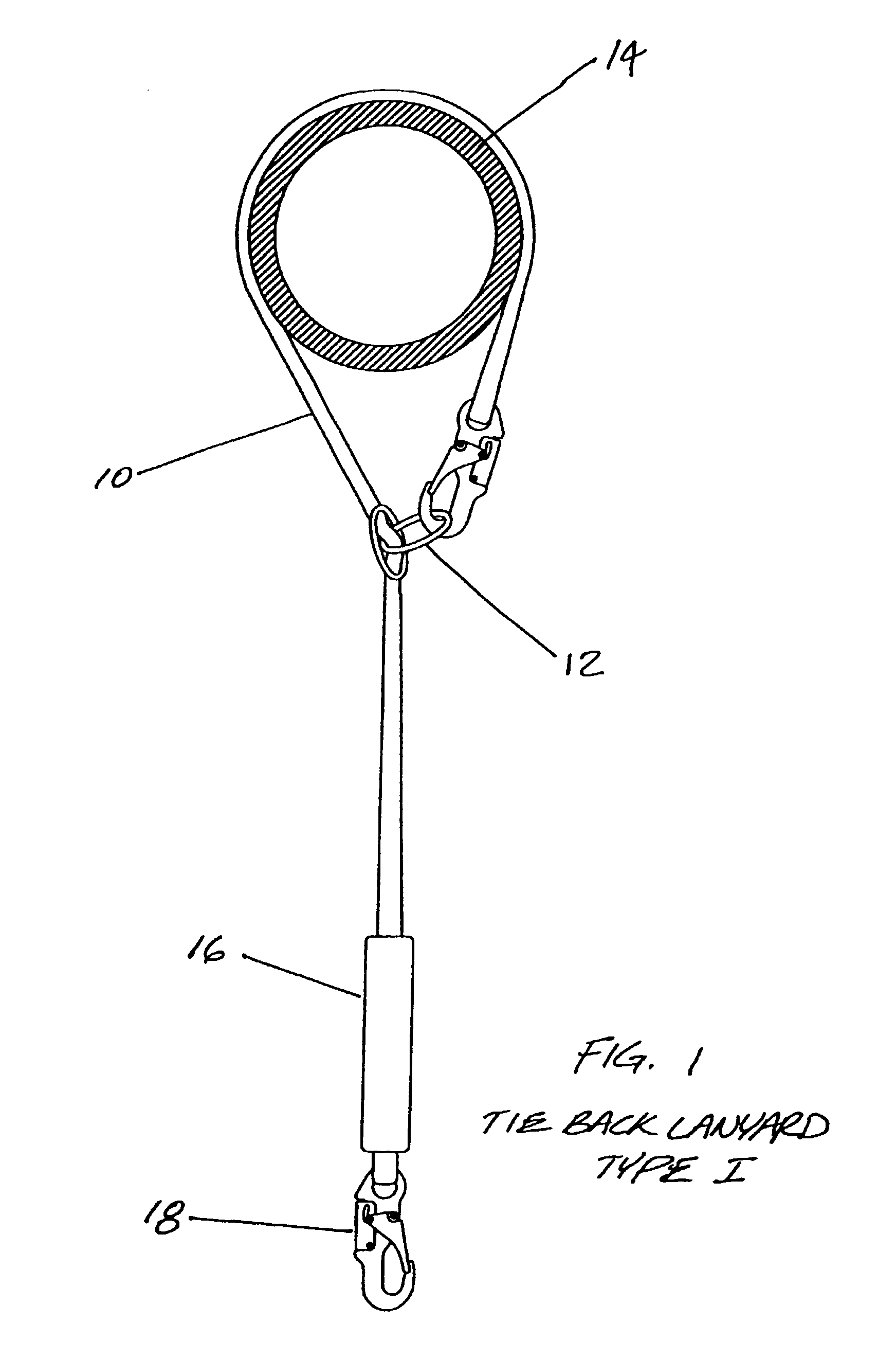
[0041]Turning now to FIGS. 1 through 3 illustrates the tie back snap geometry, use, and assembly according to the preferred embodiment of this invention. Referring to FIG. 1 the tie back lanyard Type 1(10) is shown attached to the tie back ring (12). The beam to which it is attached is a round pipe (14). The shock absorbing tie back lanyard (10) is shown with an integral shock absorber (16) and harness snap (18).

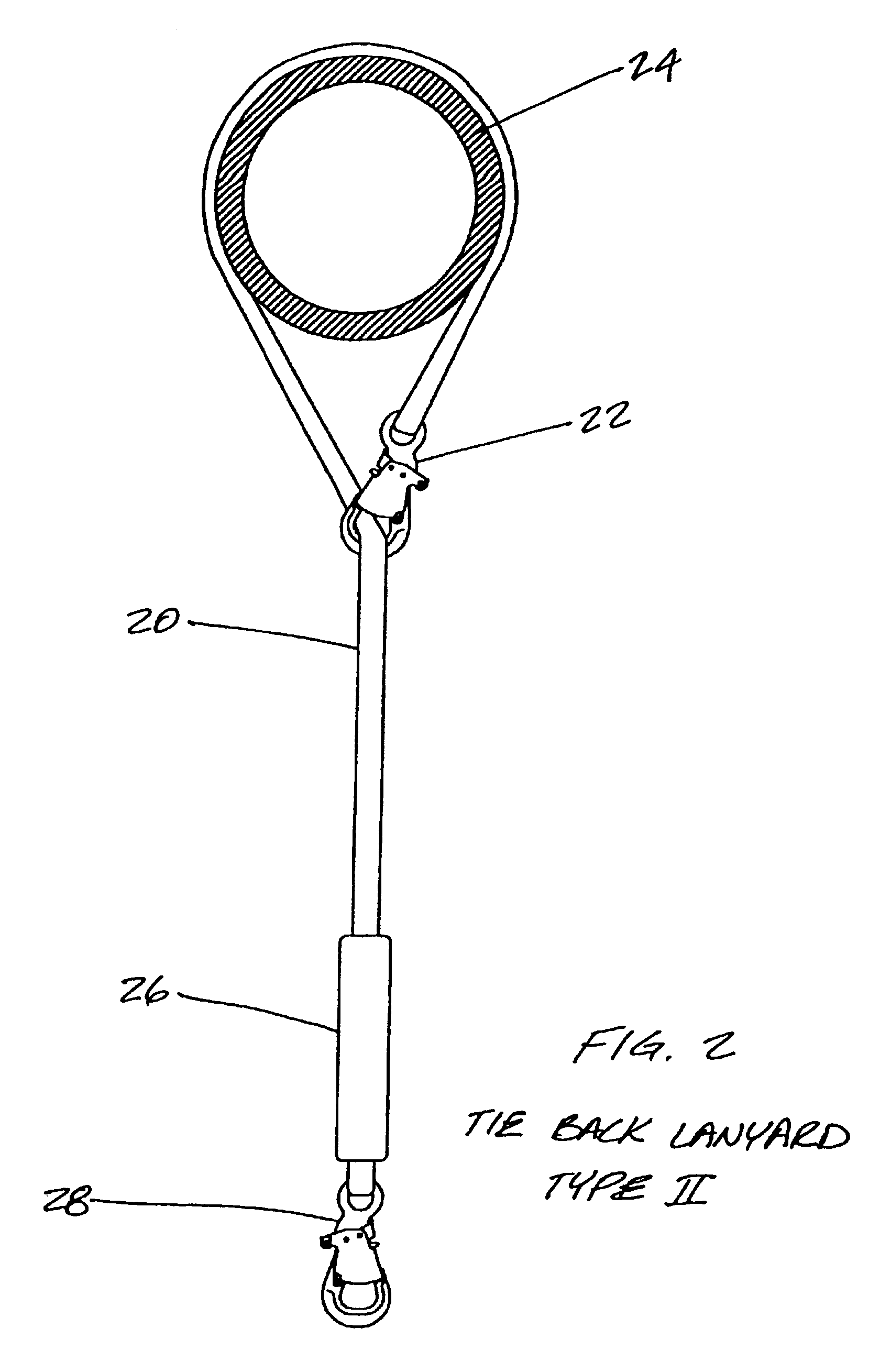
[0042]FIG. 2 shows the tie back lanyard Type II (20) with an integral tie back snap (22) positioned aroun...


PUM


Abstract

A snap hook having a J-shaped body, a gate that is pivotable about a pivot point that is near the first end of the shank, and a movable locking pin located near the second end of the shank. The locking pin is moved by least one parallel bar that is generally parallel to the shank and extends along the shank. Connected to the locking pin is a movable thumb grip that when moved urges the parallel bar to move the locking pin. The locking gate further having a recessed portion positioned near the second end of the shank and a closure portion positioned near the nose of the hook body, the closure portion and the recessed portion being at about the same distance from the pivot point, the recessed portion being adapted to cooperate with the locking pin so that when the locking pin is moved by the parallel bar the gate is released so that the gate can pivot about the pivot point.

Description

REFERENCE TO RELATED APPLICATIONS[0001]This application claims the benefit of my provisional application having Ser. No. 60 / 314,405, filed Aug. 23, 2001, now abandoned.BACKGROUND OF THE INVENTION[0002](a) Field of the Invention[0003]This invention generally relates to a safety hook and attachment system for connecting the safety hook to a harness.[0004]More particularly, but not by way of limitation, to a hook with a gate that prevents unwanted release of the hook and allows the gate to cooperate with the hook in a synergistic manner.[0005](b) Discussion of Known Art[0006]There is a large variety of safety hooks or “tie back” snap hooks that are designed for use as safety equipment. These hooks typically include a J-shaped hook portion that includes a gate that closes the mouth of the hook in order to prevent the inadvertent release of the hook.[0007]The primary purpose of these hooks is to tether a worker to a support structure in order to prevent an unrestrained fall to the ground...

Claims


Application Information

Patent Timeline
Patent Type & Authority Patents(United States)
IPC IPC(8): F16B45/00F16B45/02
CPCF16B45/02Y10T24/4534Y10T24/45372F16B45/026F16B45/029
Inventor CHOATE, GARY E.
Owner RELIANCE INDUSTRIES LIMITED
Why Eureka
Try Eureka