
Two-port ethernet line extender

a technology of ethernet line extension and two-port ethernet, which is applied in the direction of repeater circuits, line-transmission details, data switching networks, etc., can solve the problems of insufficient reliability of adoption of this standard, insufficient cost-effective alternative schemes such as optical fiber, and serious concern about power consumption, etc., to achieve the maximum signal distance, extend the electrical communication distance of digital data signals, and low capacitance

Inactive Publication Date: 2009-07-07
RATEZE REMOTE MGMT LLC
View PDF14 Cites 1 Cited by
  • Summary
  • Abstract
  • Description
  • Claims
  • Application Information

AI Technical Summary

Benefits of technology

[0007]According to the invention, an apparatus is provided for deployment in an outdoor environment for extending the electrical communication distance of digital data signals. The apparatus includes electrical isolation means for various electromagnetic effects and a high speed pulse reshaper and repeater. The isolation means includes low capacitance electric pulse suppression means so that maximum signal distance can be achieved without loss of usable pulse shape and isolation transformers on differential signal pairs that retain magnetization at elevated temperatures so that signals are not blocked. As a further feature, extended logic is included whereby the type of signals can be distinguished for speed and duplex settings, thus allowing the apparatus to be daisy-chained with like apparatus or used between a termination and a line.

Problems solved by technology

Moreover, power consumption becomes a serious concern because power must be supplied and distributed by the outdoor network.
Alternative schemes such as optical fiber are not cost effective for all applications, particularly over relatively short distances of several hundred meters.
For extended operation between −40 C and +85 C, which is more typical of actual experience in some environments, adoption of this standard would be inadequate for reliable operation.

Method used


Image

  • Two-port ethernet line extender
  • Two-port ethernet line extender
  • Two-port ethernet line extender

Examples


Embodiment Construction

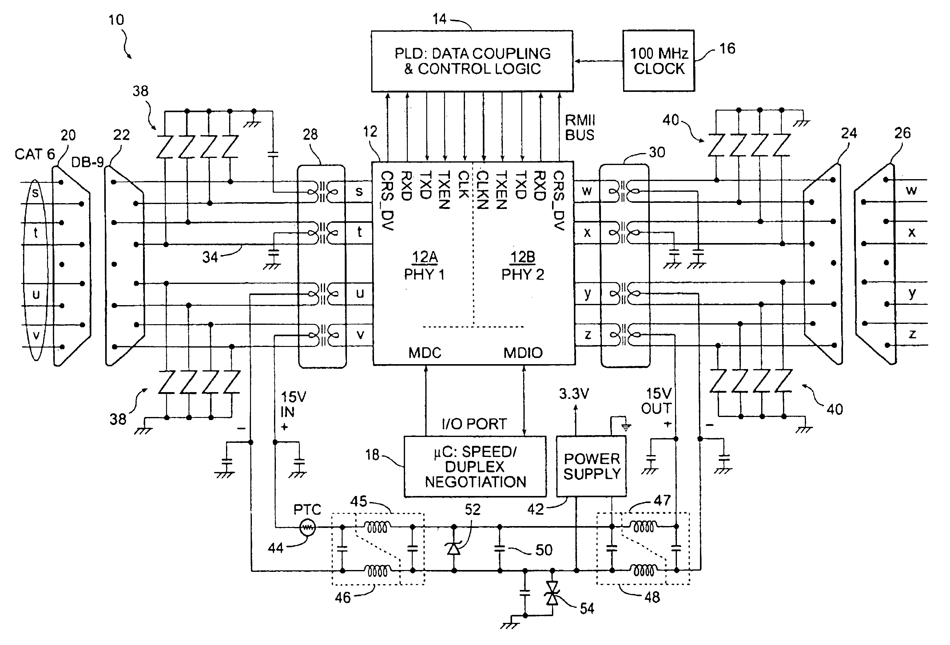
[0013]FIG. 1 is a block diagram of a line extender 10 according to the invention. The line extender 10 is built around a two port pulse shaping and repeating circuit set (PHY 1) 12A and (PHY 2) 12B for shaping and repeating pulses. This circuit set 12 is an integrated circuit combining sets of low-power physical layer transceiver and protocol control devices.

[0014]A specific embodiment for use in a 10 / 100 MBPS application is a Model AC104QF PHY quad (four element) device manufactured by Broadcom, Inc. of Irvine, Calif. This circuit is compliant with specific standards, namely the IEEE 802.3u specification and the RMII (Reduced Media Independent Interface) specification. The 10 / 100 MBPS PHY typically uses two unshielded twisted pairs for each transmission port, one pair dedicated to transmit signals (pairs t and w) and a second pair to receive signals (pairs s and x). The other two pairs (u / v and y / z) may be unused for data or they may be used to extend a second 10 / 100 MBPS line conn...


PUM


Abstract

An apparatus for deployment in an outdoor environment for extending the electrical communication distance of digital data signals includes electrical isolation means for various electromagnetic effects and a high speed pulse reshaper and repeater. The isolation means includes low capacitance electric pulse suppression means so that maximum signal distance can be achieved without loss of usable pulse shape and isolation transformers on differential signal pairs that retain magnetization at elevated temperatures so that signals are not blocked. As a further feature, extended logic is included whereby the type of signals can be distinguished, thus allowing the apparatus to be daisy-chained with like apparatus or used between a termination and a line.

Description

CROSS-REFERENCES TO RELATED APPLICATIONS[0001]Not ApplicableSTATEMENT AS TO RIGHTS TO INVENTIONS MADE UNDER FEDERALLY SPONSORED RESEARCH OR DEVELOPMENT[0002]Not ApplicableREFERENCE TO A “SEQUENCE LISTING,” A TABLE, OR A COMPUTER PROGRAM LISTING APPENDIX SUBMITTED ON A COMPACT DISK[0003]Not ApplicableBACKGROUND OF THE INVENTION[0004]This invention relates to digital data communications over distance-limited wire media. In particular, this invention relates to an apparatus for extending the propagation distance of digital data signals.[0005]There is a need to provide means to extend the effective distance over which digital data signals are communicated via wire in an outdoor environment. Distances may be greater than be supported by the conventional routers and switches. For example, known implementations of 100 BASE-TX physical layer integrated circuits such as the Broadcom AC104QF (from Broadcom, Inc.) typically handle only up to 150 m (492 ft.) of Category 5 cabling at room temper...

Claims


Application Information

Patent Timeline
Patent Type & Authority Patents(United States)
IPC IPC(8): H04J3/08H04L12/46
CPCH04L12/4604
Inventor BUTLER, KENT A.SCHURIG, ALMA K.
Owner RATEZE REMOTE MGMT LLC
Learn More