
Calibration method for slice level of zero cross signal and method of producing track-crossing signal

a zero cross signal and slice level technology, applied in the direction of digital signal error detection/correction, instruments, recording signal processing, etc., can solve the problem that the disadvantage of the prior method of compensating for the slice level does not respond dynamically to the change of the track-crossing signal

Inactive Publication Date: 2009-07-07
LAI RONNIE
View PDF8 Cites 21 Cited by
  • Summary
  • Abstract
  • Description
  • Claims
  • Application Information

AI Technical Summary

Problems solved by technology

Therefore, the performance of track seeking and track locking will affect the speed and stabilization of CD-ROM drive.
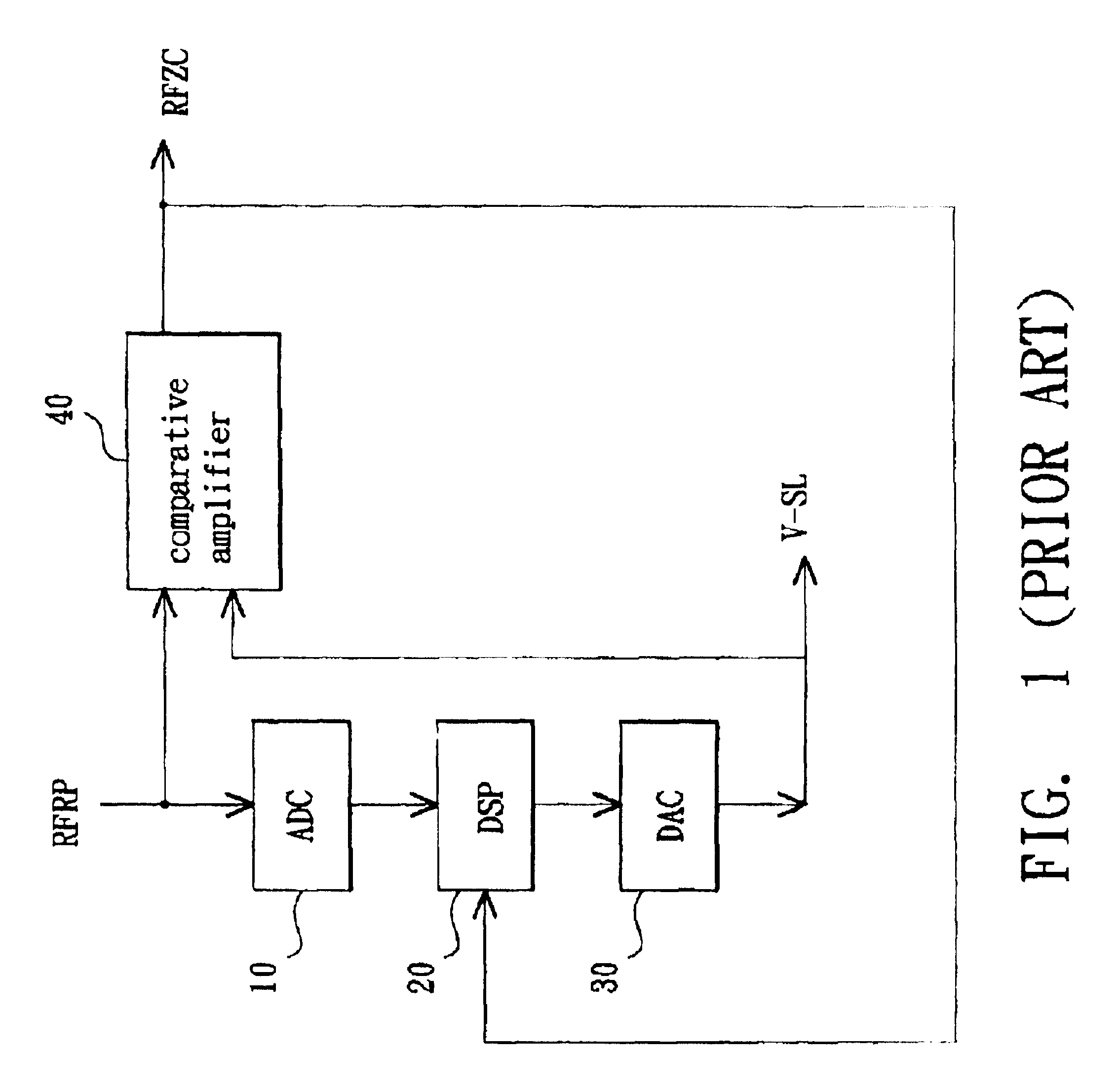
When V_SL is not correct, the RFZC signal will be incorrect so that the CD-ROM drive will have some wrong or bad performance.
In that prior art, the disadvantage of the prior method of compensating for the slice level does not respond to the change of the track-crossing signal dynamically.
Therefore, the bias voltage will need more time to follow the change of the track-crossing signal when the change of the track-crossing signal is rather violent.
However, there are two disadvantage of using low pass filter.
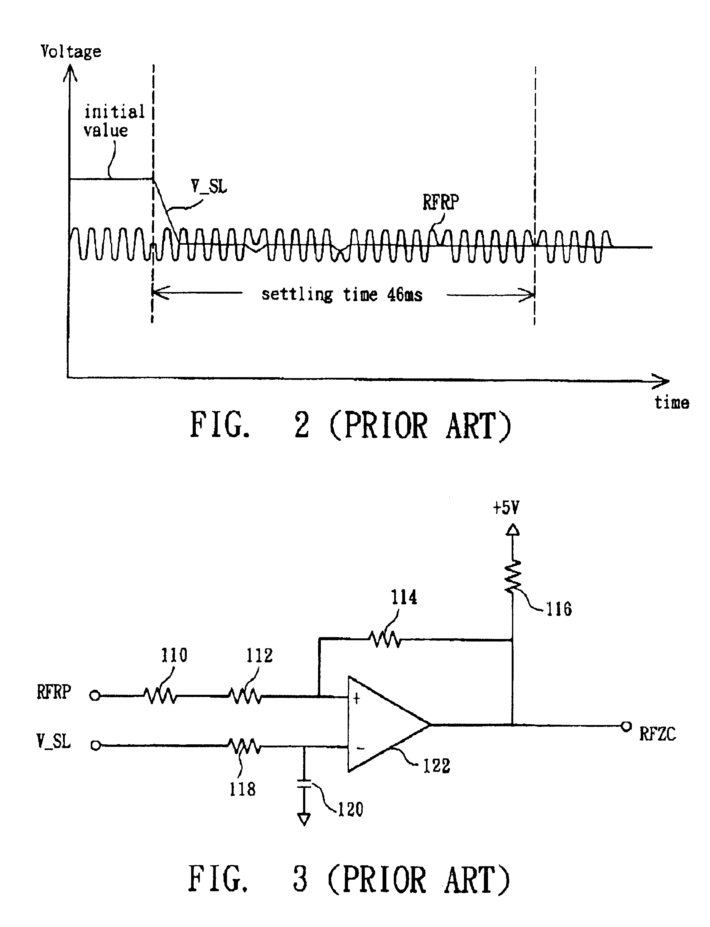
The first disadvantage is that the settling time is too long and the second disadvantage is that the Schmitt trigger will induce the positive cycle and the negative cycle of the RFZC signal to be asymmetrical.
The two disadvantages will affect the performance of the CD-ROM drive and induce the malfunction of CD-ROM drive.

Method used


Image

  • Calibration method for slice level of zero cross signal and method of producing track-crossing signal
  • Calibration method for slice level of zero cross signal and method of producing track-crossing signal
  • Calibration method for slice level of zero cross signal and method of producing track-crossing signal

Examples


Embodiment Construction

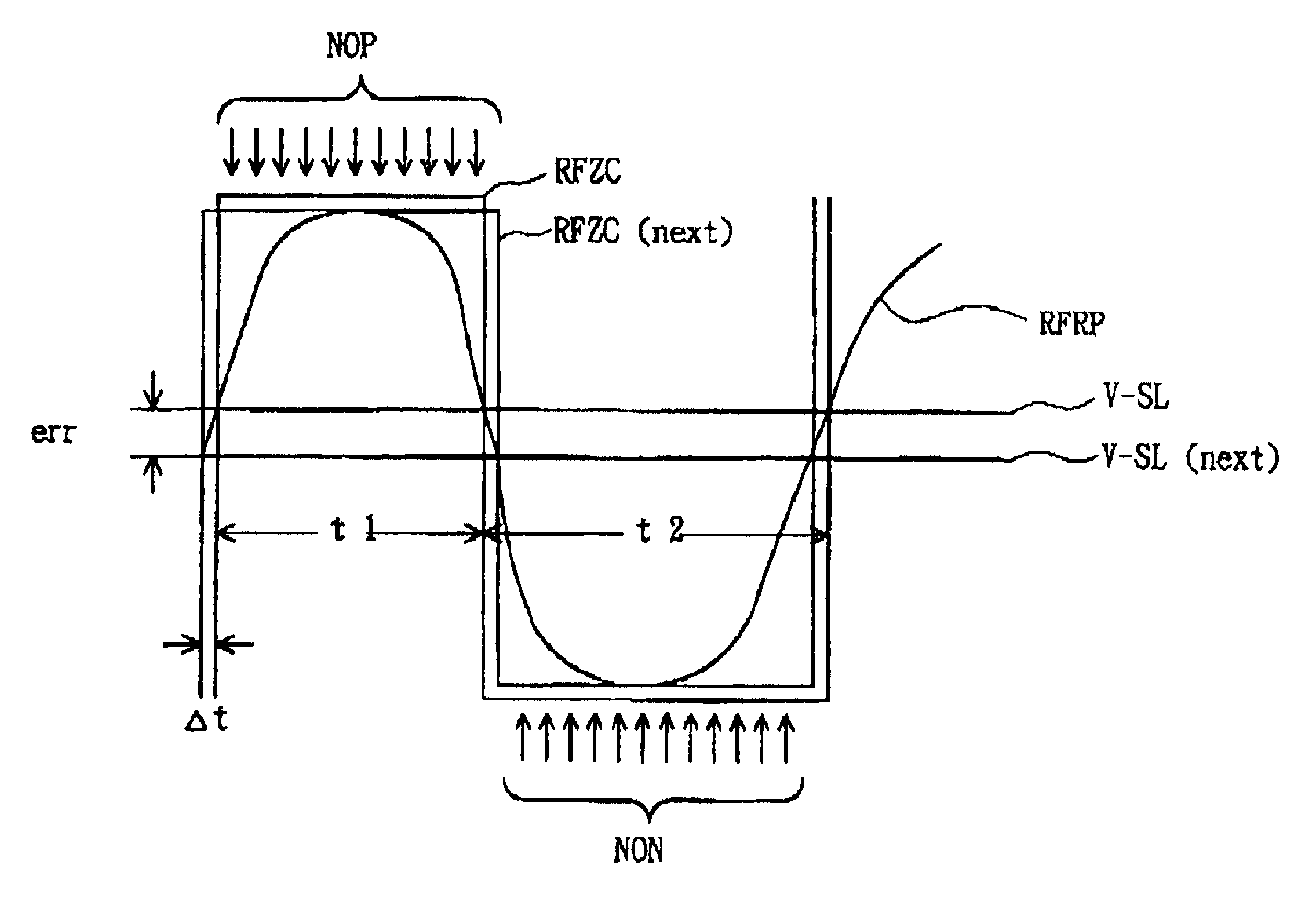
[0020]In the embodiment, the RFZC signal is sampled and counted by a high frequency, for example, about 1.4 MHz. Therefore, the count number in a positive cycle is defined as NOP and the count number in a negative cycle is defined as NON. The definition of NOP and NON are shown in FIG. 5.

[0021]Referring to FIG. 5, which shows a timing diagram of the slice level according to an embodiment of the present invention. According to the description above, the digital signal processor generates a V_SL from the RFRP signal and then the RFZC signal is generated by the RFRP signal and the V_SL through the comparative amplifier. Afterward, sampling the RFZC signal and calculation are performed. Then the result of calculation is delivered to the digital signal processor. According to the calculation equation, the error value is calculated by the digital signal processor to adjust a next V_SL.

[0022]The equations of calculating the RFRP signal and the RFZC signal to adjust the next error value of ...


PUM

PropertyMeasurementUnit
settling timeaaaaaaaaaa
frequencyaaaaaaaaaa
current sliceaaaaaaaaaa

Abstract

A calibration method for a slice level of zero cross signal and a method of producing zero cross signal are disclosed. In this invention, the positive cycle and the negative cycle of the zero cross signal are sampled to obtain an error value related to the slice level due to asymmetry of the zero cross signal. By this invention, the asymmetry between the positive cycle and the negative cycle of the zero cross signal can be adjusted.

Description

FIELD OF THE INVENTION[0001]The present invention relates to a calibration method for a slice level of zero cross signal and a method of producing track-crossing signal. More particularly, the invention relates a calibration method for slice level of radio frequency zero cross (RFZC) signal and a method of adjusting the slice level of the RFZC signal by sampling half cycle of RFZC signal.BACKGROUND OF THE INVENTION[0002]Due to the advancement of science and continuous development of multimedia, CD-ROM drive has become very popular. The main advantage of CD is high capacity to save data so the speed and the stabilization of CD-ROM drive are very important. When a CD-ROM drive reads data, there is a need for track seeking and track locking. Therefore, the performance of track seeking and track locking will affect the speed and stabilization of CD-ROM drive. In track seeking and locking, radio frequency ripple (RFRP) signal and RFZC signal are very important.[0003]Referring to FIG. 1, ...

Claims


Application Information

Patent Timeline
Patent Type & Authority Patents(United States)
IPC IPC(8): G11B7/005G11B7/085G11B27/10
CPCG11B7/08541
Inventor LAI, RONNIE
Owner LAI RONNIE
Learn More