
Alternating current light emitting diode for preventing generation of harmonic wave and stroboflash

A light-emitting diode and stroboscopic technology, applied in the direction of light source, electric light source, electric light source, etc., can solve the problems of power system voltage and current instability, long AC current time, flickering, etc., to improve the stroboscopic phenomenon and prevent harmonics The effect of wave current

Inactive Publication Date: 2011-03-23
FORWARD ELECTRONICS CO LTD
View PDF0 Cites 0 Cited by
  • Summary
  • Abstract
  • Description
  • Claims
  • Application Information

AI Technical Summary

Problems solved by technology

In order to be more widely used, there is currently an AC light-emitting diode (AC LED), which can be directly plugged into 110V AC voltage of 60Hz or higher frequency. This technology has effectively solved the problem that the LED cannot be directly connected to the AC power supply problem of use
[0003] However, although AC light-emitting diodes have the advantage of being directly connected to the mains, if the voltage and current of the power supply system are unstable, the brightness of the AC light-emitting diodes will change significantly, and there will be flickering problems that can be recognized by the human eye.
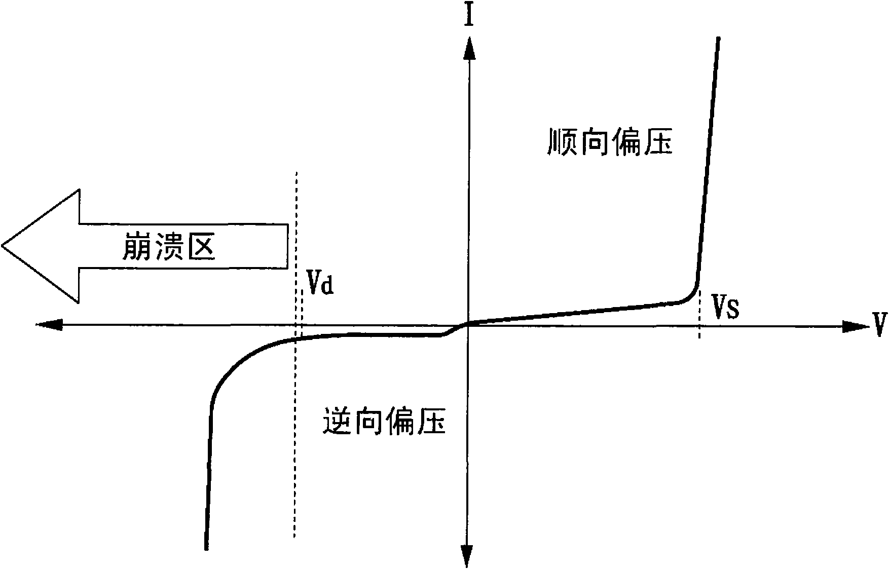
In addition, since the AC power provided by the mains itself is a positive and negative half-cycle AC voltage signal, if the overall forward starting voltage of the AC LED module is too high, the AC current flowing through the AC LED will be at Zero-Crossing If the time is too long, stroboscopic phenomenon will also occur

Method used


Image

  • Alternating current light emitting diode for preventing generation of harmonic wave and stroboflash
  • Alternating current light emitting diode for preventing generation of harmonic wave and stroboflash
  • Alternating current light emitting diode for preventing generation of harmonic wave and stroboflash

Examples


Embodiment Construction

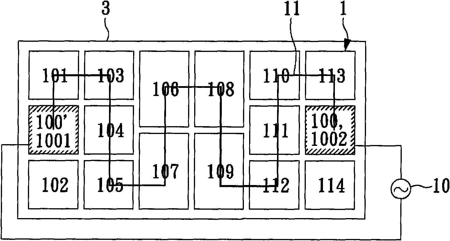
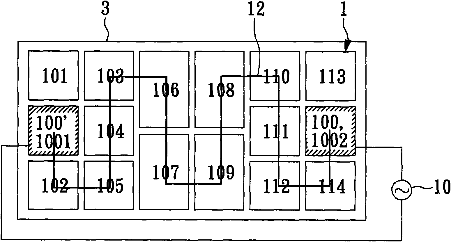
[0016] Please refer to FIG. 1 first. FIG. 1 is a schematic diagram of an AC light-emitting diode that prevents harmonics and stroboscopic generation in the present invention. Taking a preferred embodiment of the present invention as an example, the light-emitting diode 1 includes fourteen light-emitting diode microcrystals. 101-114, and an AC power receiving end 100. These fourteen light-emitting diode microchips 101-114 and the AC power receiving end 100 are integrated on the chip 3 with the same packaging structure.

[0017] As shown in Figure 1(a), LED microcrystal grains 101, LED microcrystal grains 103, LED microcrystal grains 104, LED microcrystal grains 105, LED microcrystal grains 107, and LED microcrystal grains 106 , LED microcrystal 108, LED microcrystal 109, LED microcrystal 112, LED microcrystal 111, LED microcrystal 110, and LED microcrystal 113 are connected in series to form the first group of LEDs 11;

[0018] As shown in Figure 1(b), LED microcrystals 114, ...


PUM


Abstract

The invention relates to an alternating current light emitting diode for preventing the generation of harmonic wave and stroboflash, which comprises an alternating current power supply receiving end for receiving an alternating current power supply containing a positive cycle power supply and a negative cycle power supply, a first group of light emitting diodes conducted in the positive cycle power supply and closed in the negative cycle power supply, and a second group of light emitting diodes conducted in the negative cycle power supply and closed in the positive cycle power supply, wherein the integral starting voltage of the first group and the second group of light emitting diodes is lower than the peak value of the alternating current power supply and beyond a default value, and the integral bearable inverse voltage is higher than the peak value of the alternating current power supply to promote the power factors and prevent the generation of the harmonic wave; and thus, the stroboflash phenomenon of the alternating current light emitting diodes is effectively improved.

Description

technical field [0001] The invention relates to an AC light-emitting diode, in particular to an AC light-emitting diode suitable for preventing harmonics and flicker. Background technique [0002] Light-emitting diodes are currently one of the key development projects in the technology industry. The process technology of light-emitting diodes has matured, and now there are light-emitting diodes in blue, white, pink, purple, red, orange, green, yellow and other colors. Light-emitting diodes are becoming more and more common in applications. For example, light-emitting diodes can be used in all lamp bodies that can be illuminated, such as flashlights, automotive lighting, and lighting decorations. In order to be more widely used, there is currently an AC light-emitting diode (AC LED), which can be directly plugged into 110V AC voltage of 60Hz or higher frequency. This technology has effectively solved the problem that the LED cannot be directly connected to the AC power suppl...

Claims


Application Information

Patent Timeline
IPC IPC(8): F21S2/00F21V23/00H05B37/00H05B37/02H01L25/075F21Y101/02
Inventor 蓝培轩陈瑞鸿杨仁华蓝钰邴
Owner FORWARD ELECTRONICS CO LTD
Learn More