Method for replacing a tacking fastener

a technology of tacking fasteners and fasteners, which is applied in the field of metal working, can solve the problems of splinters, parts of the head that can scratch the surface of the outer workpiece, and the area of the aircraft is not fully accessible, so as to reduce the volume of fastener materials and reduce the size and amount of chips produced

Inactive Publication Date: 2007-04-24
ALLFAST FASTENING SYST
View PDF107 Cites 19 Cited by
  • Summary
  • Abstract
  • Description
  • Claims
  • Application Information

AI Technical Summary

Benefits of technology

[0010]The diameter of the conical shank head is smaller than the diameter of the drill so that part of the head does not become attached to the drill bit and scratch the workpiece. The conical shape of the head also reduces the volume of fastener material to further reduce the size and amount of chips produced during the drilling process. The tightly engaged shank prevents the fastener from rotating during the drilling operation.

Problems solved by technology

Some areas of the aircraft are not fully accessible, thereby requiring the use of a blind rivet which can be installed from only one side of a workpiece.
It has been found that drilling temporary blind fasteners of the prior art may create splinters and portions of the head that can scratch the surface of the outer workpiece.

Method used


Image

  • Method for replacing a tacking fastener
  • Method for replacing a tacking fastener
  • Method for replacing a tacking fastener

Examples


Embodiment Construction

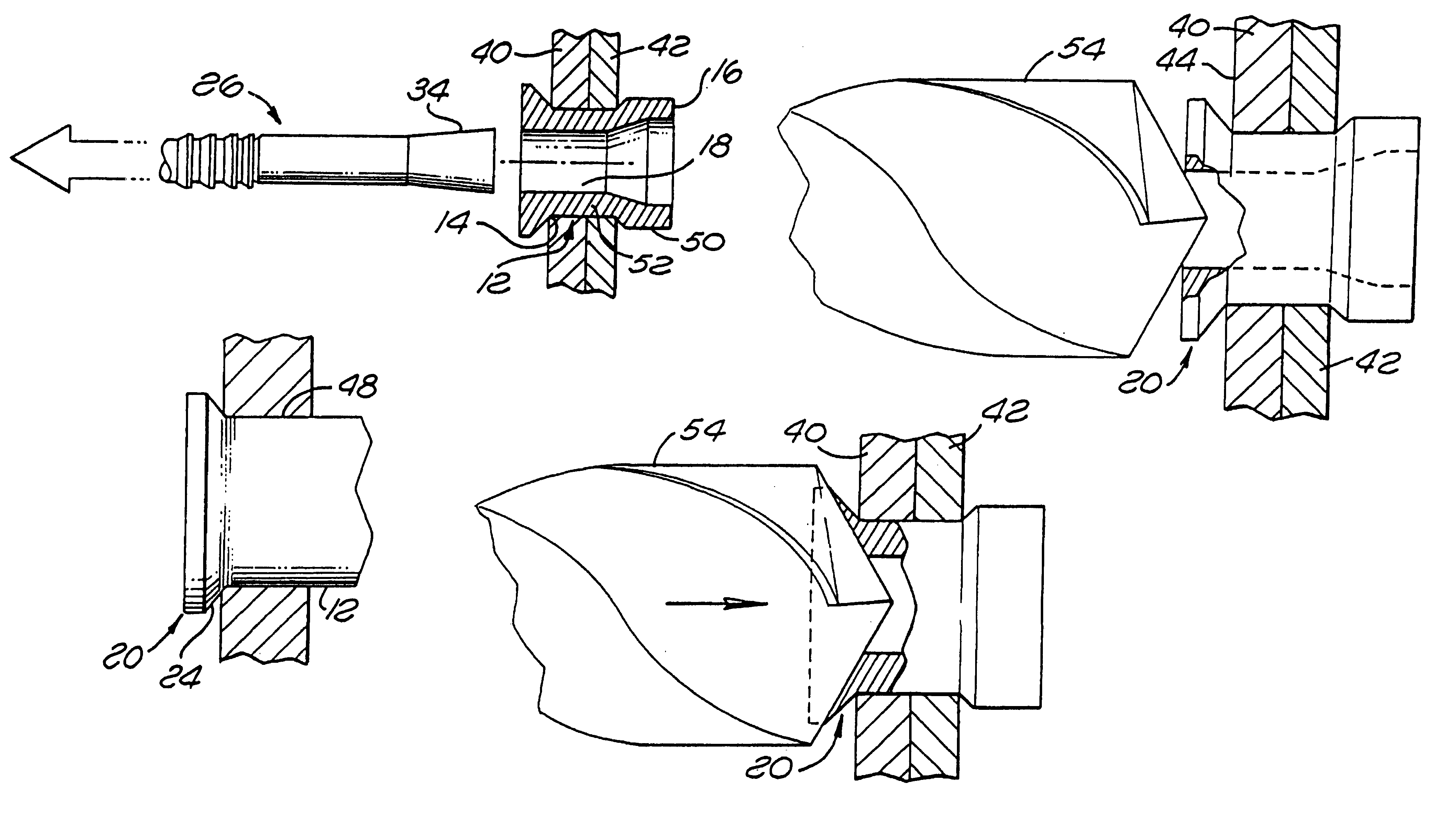
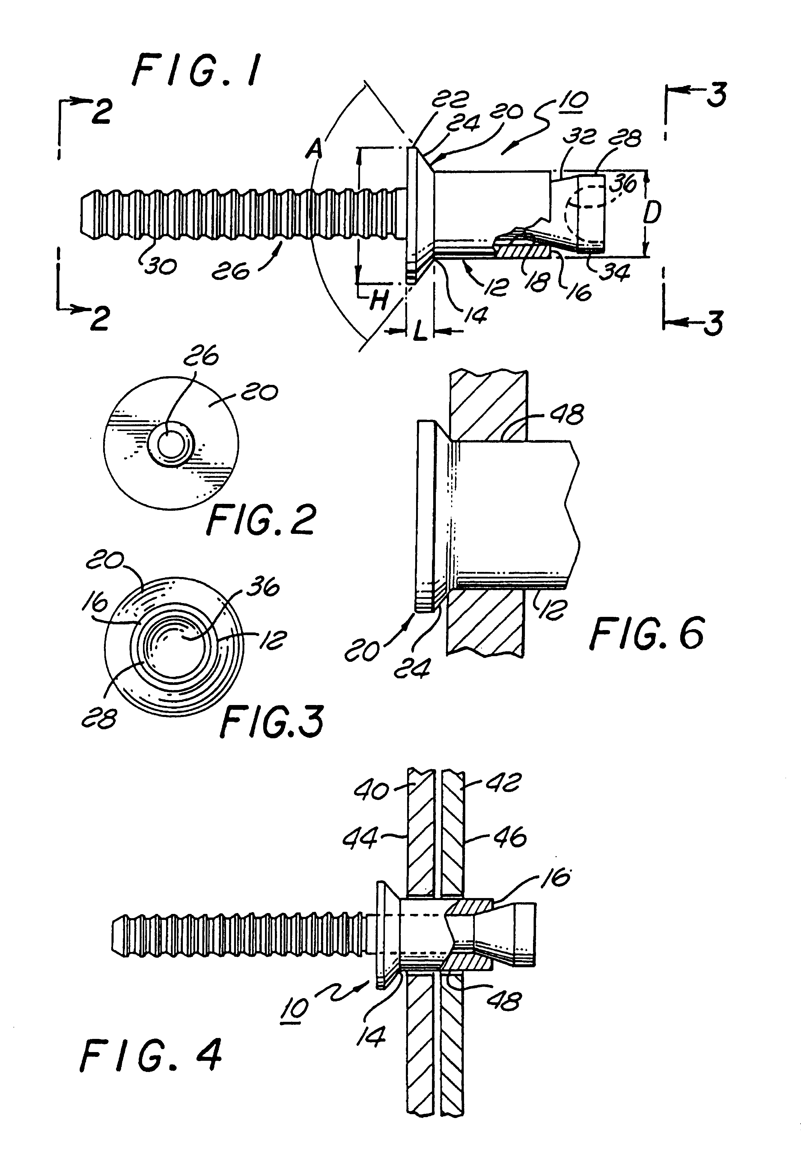
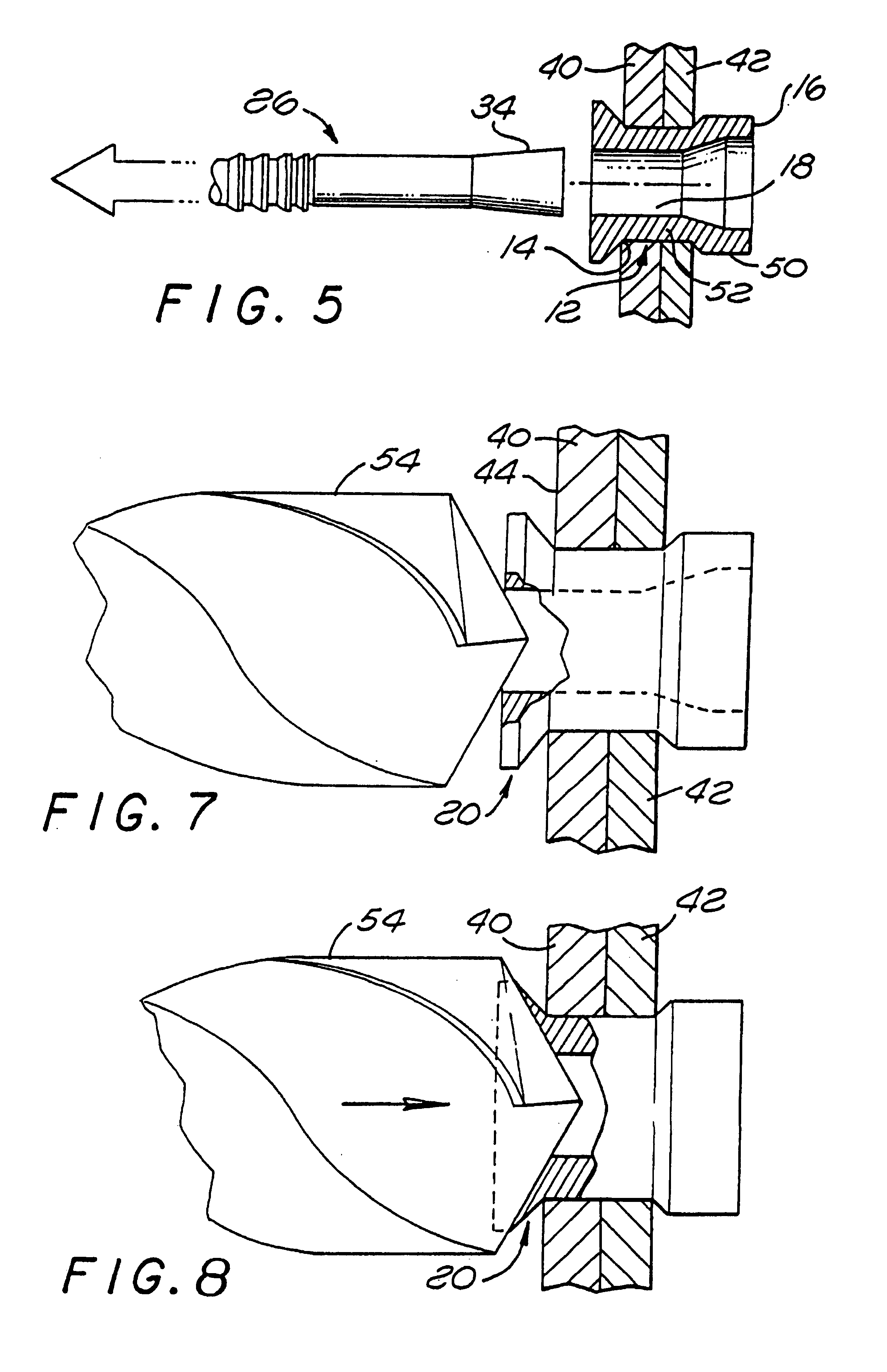
[0020]Referring to the drawings more particularly by reference numbers, FIGS. 1 through 3 show a tacking fastener 10 of the present invention. The tacking fastener 10 is typically used to temporarily fasten together two adjacent workpieces. The fastener 10 includes a shank 12 which has a first end 14, a second end 16 and an inner channel 18 that extends through the shank 12. Extending from the first end 14 of the shank 12 is a conical shaped head 20. The head 20 has an annular lip portion 22 that is separated from the first end 14 by a tapered portion 24.

[0021]The fastener 10 includes a pull stem 26 that extends through the inner channel 18 of the shank 12. The pull stem 26 has a stem head 28 that is located adjacent to the second end 16 of the shank 12. The stem 26 also has a serrated pull portion 30 that can be gripped by a pull gun (not shown) to pull the head 28 through the inner channel 18 of the shank 12. The stem head 28 may have a tapered portion 32 which leads the head 28 i...


PUM

PropertyMeasurementUnit
diameteraaaaaaaaaa
diameteraaaaaaaaaa
diameteraaaaaaaaaa

Abstract

A temporary fastener that fastens two adjacent workpieces. The fastener includes a shank that extends through a hole of the workpieces. Extending from one end of the shank is a conical shaped head. The fastener also contains a pull stem which has a head located adjacent to the blind end of the shank. The stem head is pulled through the shank to expand and tightly fasten the shank to the workpieces. The fastener is removed by drilling through the head and the shank. The diameter of the conical shank head is smaller than the diameter of the drill so that part of the head does not become attached to the drill bit and scratch the workpiece. The conical shape of the head also reduces the volume of fastener material to further reduce the size and amount of chips produced during the drilling process. The tightly engaged shank prevents the fastener from rotating during the drilling operation.A method of replacing a tacking fastener that temporarily joins two adjacent workpieces with a permanent fastener to permanently join the workpieces. A drill bit is engaged with an inner channel of the temporary fastener at a head of the fastener. The drill bit has a diameter larger than the head diameter. The head, the shank, the first workpiece, and the second workpiece are drilled through to form a hole through the workpieces. The first workpiece and the second workpiece are joined with a permanent fastener through the hole.

Description

[0001]Notice: More than one reissue application has been filed for the reissue of U.S. Pat. No. 5,689,873. The reissue applications are application Ser. Nos. 09 / 444,537 and 10 / 131,629 (the present application) which is a continuation of Ser. No. 09 / 444,537, all of which are reissues of U.S. Pat. No. 5,689,873.<?insert-end id="INS-S-00002" ?>[0002]This is a Continuation of Reissue application Ser. No. 09 / 444,537, filed Nov. 22, 1999 pending, for reissue of U.S. Pat. No. 5,689,873, filed Nov. 6, 1996 and issued Nov. 25, 1997, which issued from a Divisional application of application Ser. No. 08 / 584,111, filed Jan. 11, 1996 now abandoned.BACKGROUND OF THE INVENTION[0003]1. Field of the Invention[0004]The present invention relates to metal working and more particularly to a method for assembling that includes disassembling by destroying a temporary connector to create a hole for a permanent separate fastener for temporarily fastening two adjacent workpieces.[0005]2. Description of...

Claims


Application Information

Patent Timeline
Patent Type & Authority Patents(United States)
IPC IPC(8): B23P11/00B23B41/00F16B4/00F16B5/04F16B19/08F16B19/10
CPCB23B41/00F16B4/004F16B5/04F16B19/1045Y10T29/49943Y10T29/49963Y10T29/49821F16B19/08
Inventor LUHM, RALPH
Owner ALLFAST FASTENING SYST
Why Eureka
Try Eureka