Eureka AIR delivers breakthrough ideas for toughest innovation challenges, trusted by R&D personnel around the world.

Data transmitter and receiver of a spread spectrum communication system using a pilot channel

a technology of spread spectrum communication system and data transmitter, which is applied in the direction of orthogonal multiplex, multi-component code generation, electrical apparatus, etc., can solve the problems of weak system, complex circuitry, and difficulty in adjusting the synchronization of pn code at the receiving side, so as to minimize the pn code acquisition time, simplify the synchronization process, and spread the effect of spectrum

Inactive Publication Date: 2004-09-28
SAMSUNG ELECTRONICS CO LTD
View PDF18 Cites 41 Cited by
  • Summary
  • Abstract
  • Description
  • Claims
  • Application Information

AI Technical Summary

Benefits of technology

It is another object of the present invention to provide an improved spread spectrum communication system utilizing a pilot signal for simplifying the synchronization process and minimizing the PN code acquisition time.
It is also an object of the preset invention to provide a improved spread spectrum communication system capable of providing the transmission and reception of a spread spectrum signal with low bit error rates.

Problems solved by technology

Such systems, however, are weak due to multipath fading and narrow band noise.
In these conventional spread spectrum receivers, however, initial synchronization and synchronization tracking are often achieved through costly and complex circuitry.
Moreover, we have observed that it is difficult to adjust synchronization of the PN code at the receiving side, as the modulated PN code and not pure PN code is transmitted at the transmitting side.
Consequently, the time required to establish initial synchronization has not effectively improved.

Method used


Image

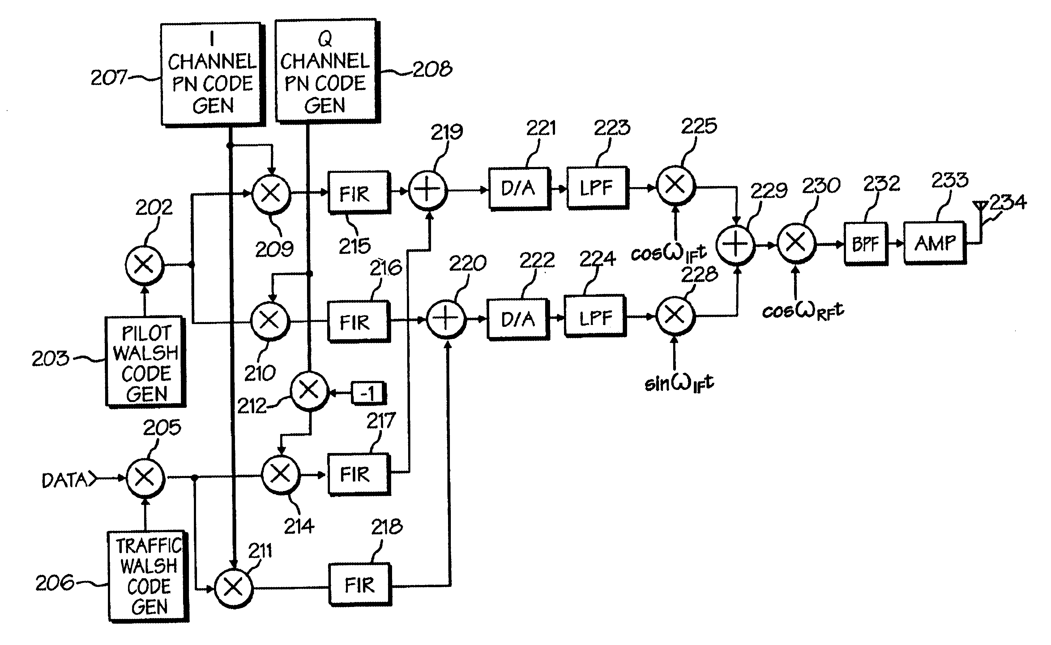
  • Data transmitter and receiver of a spread spectrum communication system using a pilot channel
  • Data transmitter and receiver of a spread spectrum communication system using a pilot channel
  • Data transmitter and receiver of a spread spectrum communication system using a pilot channel

Examples


Embodiment Construction

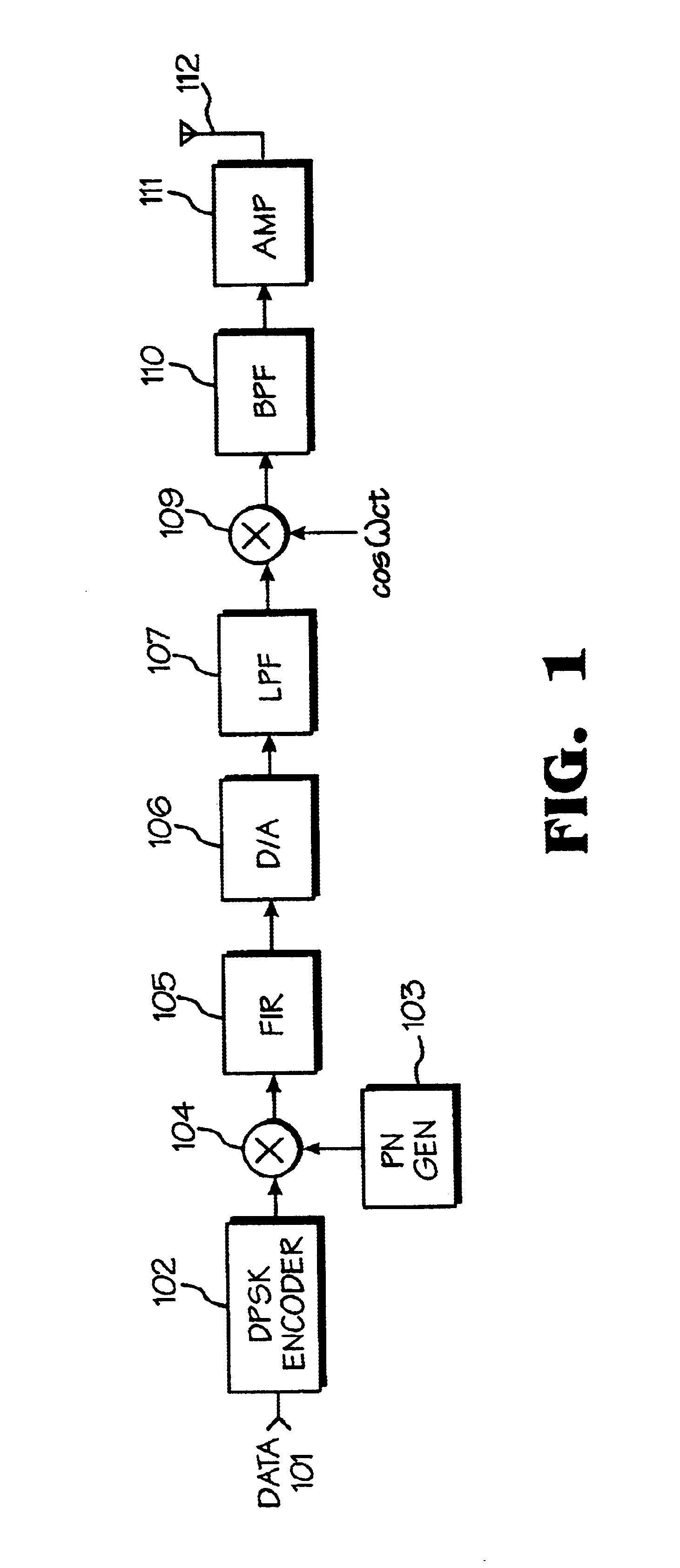
Referring now to the drawings and particularly to FIG. 1, which illustrates a typical transmitter in a spread spectrum communication system using a conventional differential phase-shift keying (DPSK) modulation technique. The transmitter includes a DPSK encoder 102 for differential-modulating input baseband data; a PN code generator 103 for generating a PN code sequence; a band spreader 104 for band spreading the differentially modulated data by multi-plying the differentially modulated data by the PN code sequence; a finite impulse response (hereinafter referred to as an "FIR") filter 105 connected to the band spreader 104, for filtering the band spreaded data; a D / A converter 106 and a LPF 107 serially connected to the FIR filter 105, for converting the band spreaded data into an analog signal and low-pass filtering the analog signal; and a mixer 109 for multiplying the output of the LPF 107 by a carrier signal cosW.sub.c t for propagation to free space through a bandpass filter (...


PUM


Abstract

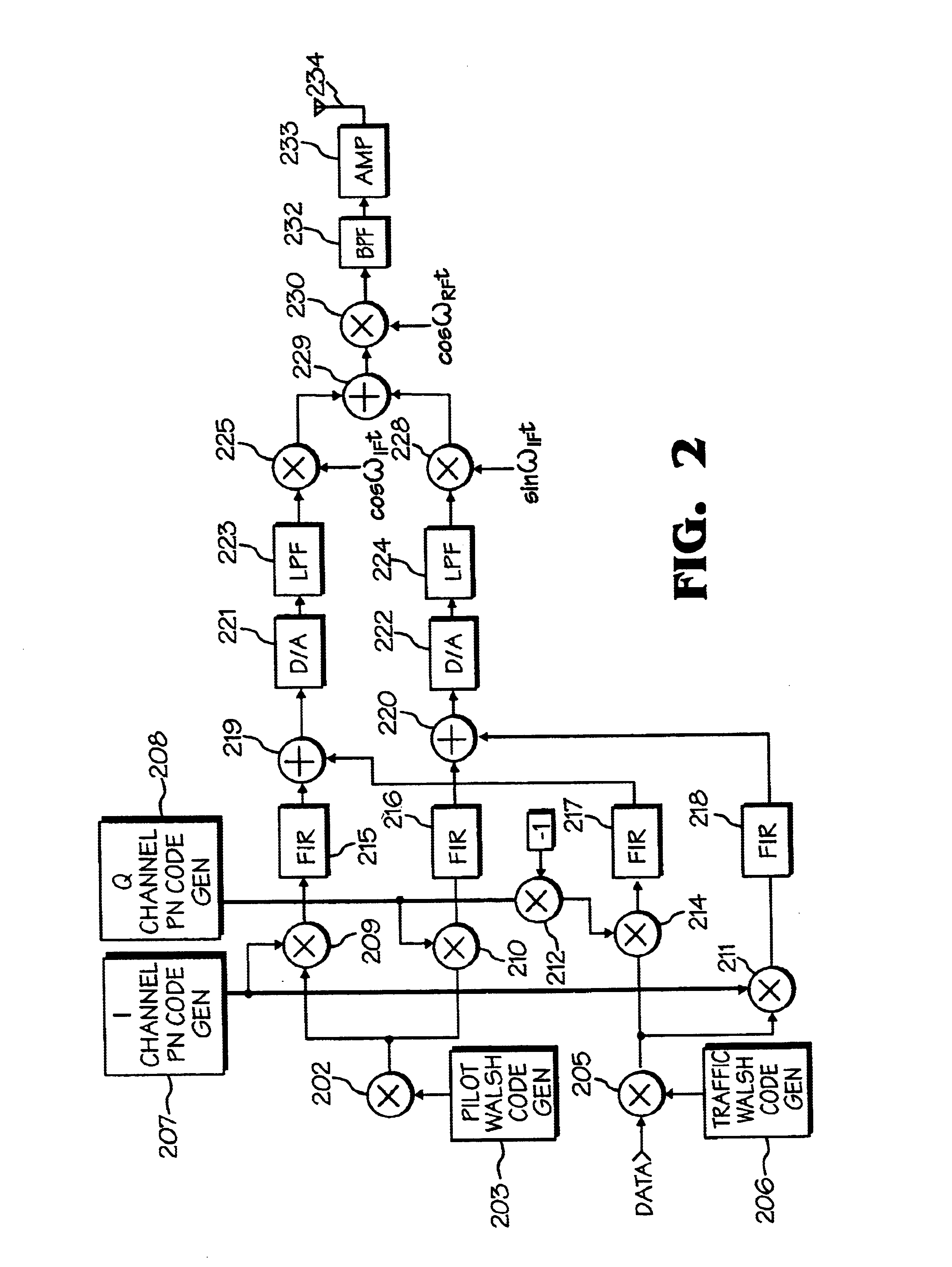
An improved spread spectrum communication system includes a transmitter and a receiver utilizing a pilot channel for the transmission of pure rather than modulated PN codes for code acquisition or tracking purposes with a lower bit error rate. The pilot signal is used to obtain initial system synchronization and phase tracking of the transmitted spread spectrum signal. At the transmitter side, a Walsh code generator, a Walsh modulator, a first PN code generator, a first band spreader, a second band spreader, finite impulse response filters, digital-analog converters, low-pass filters, an intermediate frequency mixer, a carrier mixer, a band-pass filter are used to transmit a spread spectrum signal. At the receiver side, a corresponding band-pass filter, a carrier mixer, an intermediate-frequency mixer, low-pass filters, analog-digital converters, a second PN code generator, an I channel despreader, a Q channel despreader, a PN code synchronization controller, a Walsh code generator, a first Walsh demodulator, a second Walsh demodulator, accumulator & dump circuits, a combiner, and a data decider are used to demodulate a received spread spectrum signal

Description

CROSS-REFERENCE TO RELATED APPLICATIONSThis application makes reference to, incorporates the same herein, and claims all benefits accruing under 35 U.S.C. .sctn.119 from an application for Data Transmitter And Receiver Of A Spread Spectrum Communication System Using a Pilot Channel earlier filed in the Korean Industrial Property Office on 22 Nov. 1994 and assigned Ser. No. 30743 / 1994.BACKGROUND OF THE INVENTION1. Technical FieldThe present invention relates to a spread spectrum communication system, and more particularly to data transmitter and receiver of the spread spectrum communication system using a pilot channel.2. Background ArtConventionally, narrow band modulation systems (such as for example, amplitude modulation, frequency modulation and phase shift key modulation) have been used in the field of data communication. With such systems, demodulation at the receiver can be achieved with a relatively small amount of circuitry. Such systems, however, are weak due to multipath f...

Claims


Application Information

Patent Timeline
Patent Type & Authority Patents(United States)
IPC IPC(8): H04B1/69H04B1/707H04J11/00H04J13/00H04J13/12
CPCH04B1/707H04J13/0048H04J13/12H04B1/7073H04L7/0008H04J2013/0096
Inventor KIM, JE-WOOLEE, BYEONG-HOPARK, JONG-HYEON
Owner SAMSUNG ELECTRONICS CO LTD
Why Eureka
Eureka Blog
Learn More