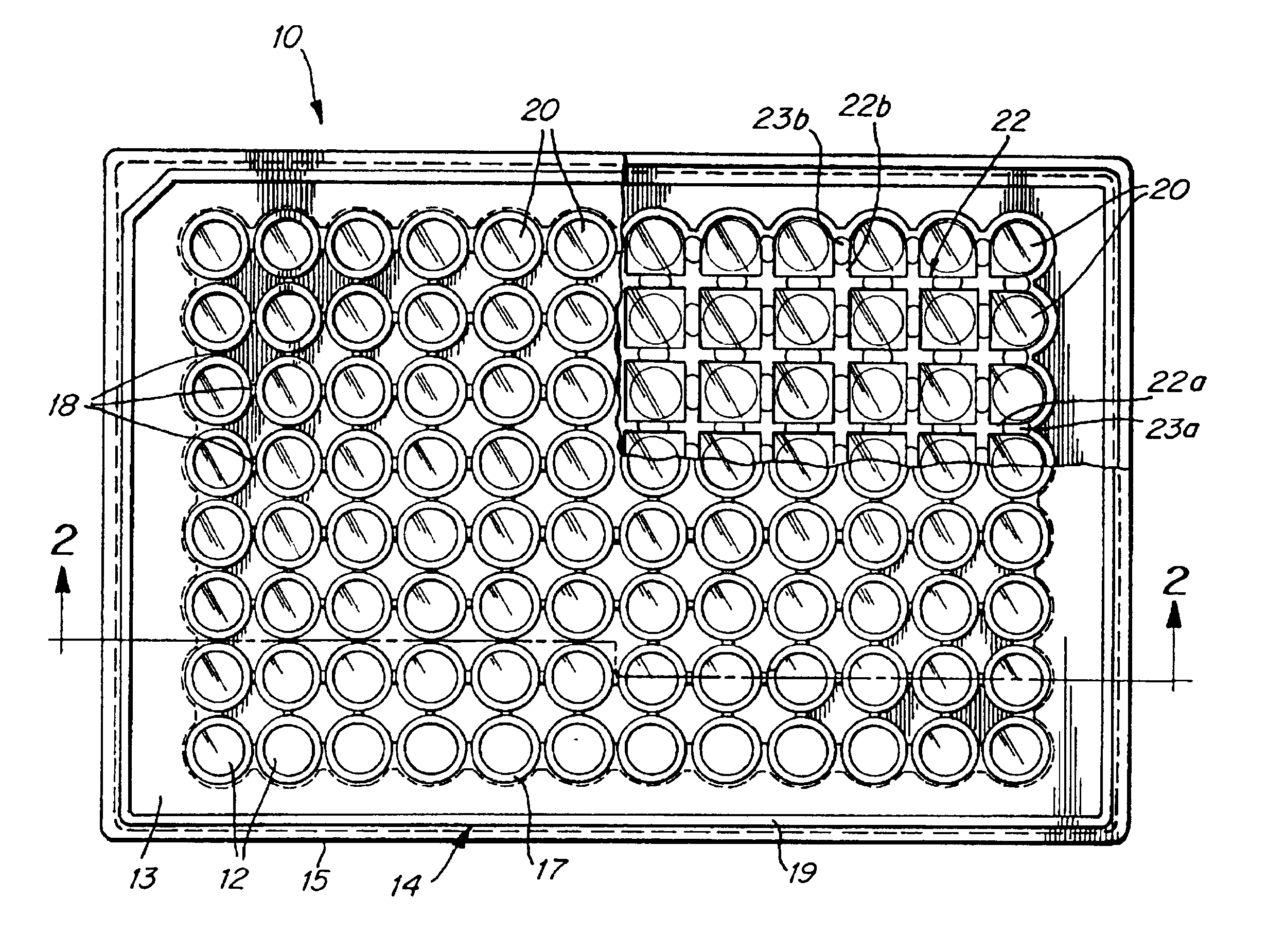
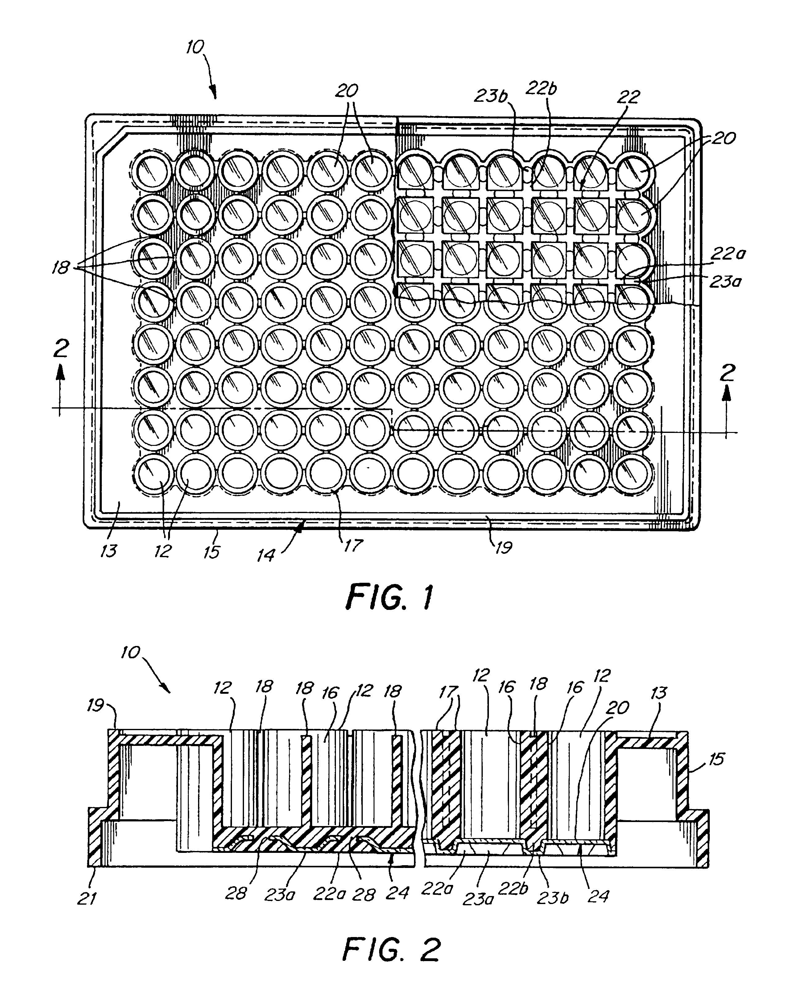
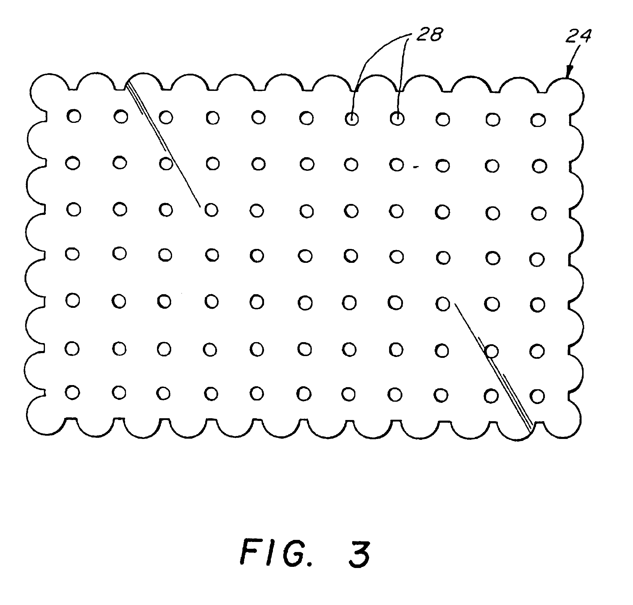
Microplates with UV permeable bottom wells
a microplate and bottom well technology, applied in the field of microplates, can solve the problems of limited progress in the manufacture of such microplates, polymeric materials with relatively high uv absorption probabilities, chemical and physical degradation of microplates,
- Summary
- Abstract
- Description
- Claims
- Application Information
AI Technical Summary
Benefits of technology
Problems solved by technology
Method used
Image

Examples
example 1
A sheet formed of a corona-treated Aclar.RTM. film having a thickness of 7.5 mils and a molecular weight of greater than 10,000 (available from AlliedSignal, Inc., 101 Columbia Road, Morristown, N.J., 07692) was placed within a rib mold piece 40 having channels disposed therein. The rib mold piece was then fitted with a well-mold piece 38. Polystyrene (purchased from BASF, located in Mount Olive, N.J.) in a molten state was injected into the cavity through the injection gate 48 at a temperature of approximately 440.degree. F. and a pressure of approximately 1200 psig. After filling the cavity with molten material, the pressure was reduced to 500 psig for approximately 6 seconds. The mold was allowed to partially cool by cooling the mold pieces to a temperature between approximately 95.degree. F. and 120.degree. F. with water. This injection / cooling process was repeated, and the mold was finally cooled and opened to remove the microplate.
PUM
| Property | Measurement | Unit |
|---|---|---|
| Length | aaaaa | aaaaa |
| Length | aaaaa | aaaaa |
| Fraction | aaaaa | aaaaa |
Abstract
Description
Claims
Application Information
 - R&D
- Intellectual Property
- Life Sciences
- Materials
- Tech Scout
- Unparalleled Data Quality
- Higher Quality Content
- 60% Fewer Hallucinations
Browse by: Latest US Patents, China's latest patents, Technical Efficacy Thesaurus, Application Domain, Technology Topic, Popular Technical Reports.
© 2025 PatSnap. All rights reserved.Legal|Privacy policy|Modern Slavery Act Transparency Statement|Sitemap|About US| Contact US: help@patsnap.com