
Garnish members having an air bag

Inactive Publication Date: 2003-05-27
TOYODA GOSEI CO LTD
View PDF6 Cites 33 Cited by
  • Summary
  • Abstract
  • Description
  • Claims
  • Application Information

AI Technical Summary

Benefits of technology

That is, if the fixing portion is installed and fixed to the body, the air bag can be installed and fixed to the body easily.
After the air bag is installed and fixed, if inflation gas is supplied into the air bag from an inflator, the air bag begins to be inflated so that it ruptures the brackets maintaining its folded condition. Further, the air bag opens the garnish bodies which are hinged to the fixing portions. Thus, the air bag can be inflated largely such that there occurs no obstacle to an activation of the air bag apparatus.
Therefore, with the garnish members according to the present invention, the air bag is temporarily fixed thereto prior to installation and fixing to the body, and if the garnish members are disposed on the body, the air bag can be disposed at a predetermined position. Thus, installation and fixing of the air bag and the garnish members to the body can be achieved easily.

Problems solved by technology

Thus, it takes much time and trouble to install the air bag and the garnish members to the body at a position in which the garnish members are disposed.

Method used


Image

  • Garnish members having an air bag
  • Garnish members having an air bag
  • Garnish members having an air bag

Examples


first embodiment

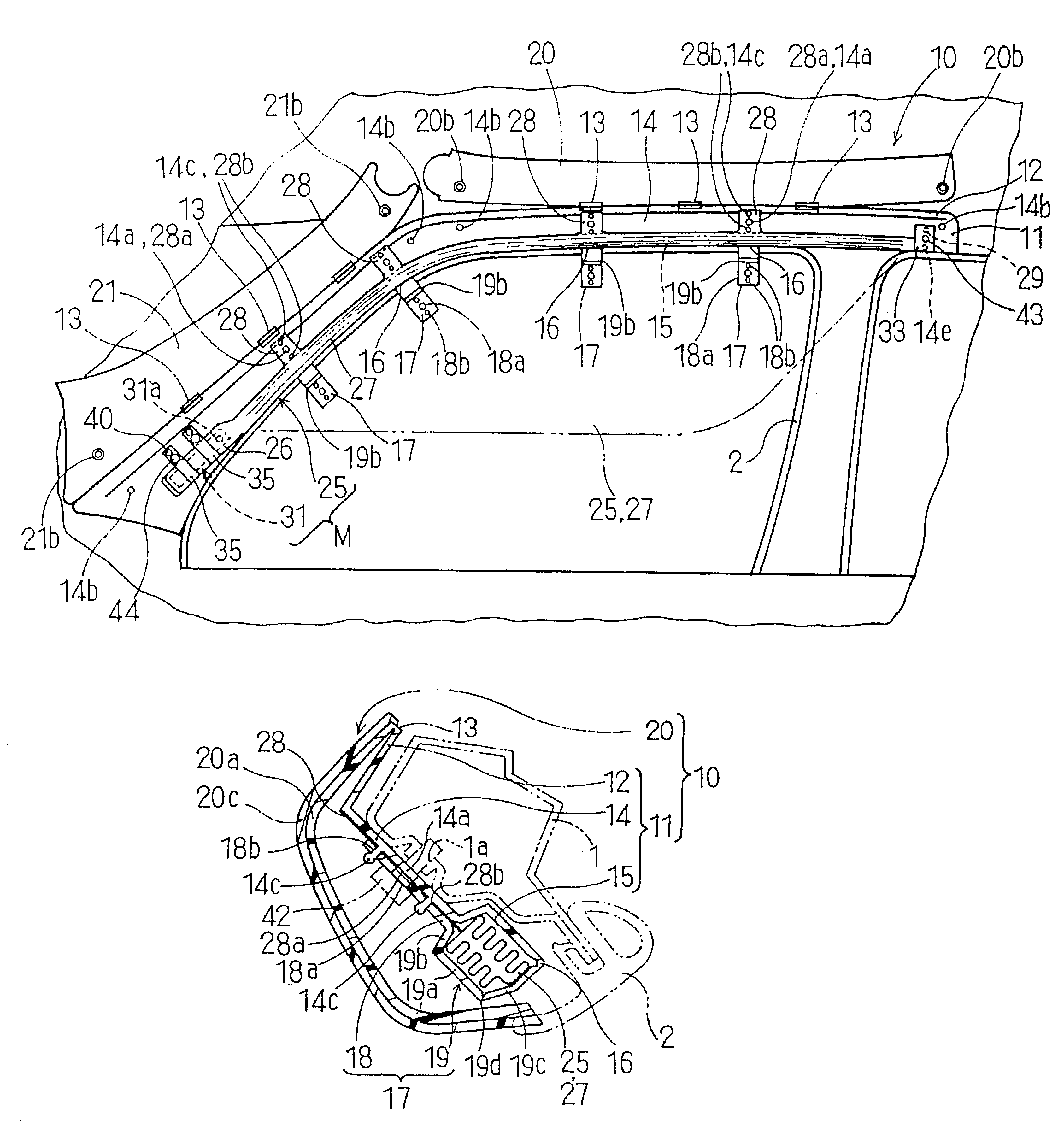
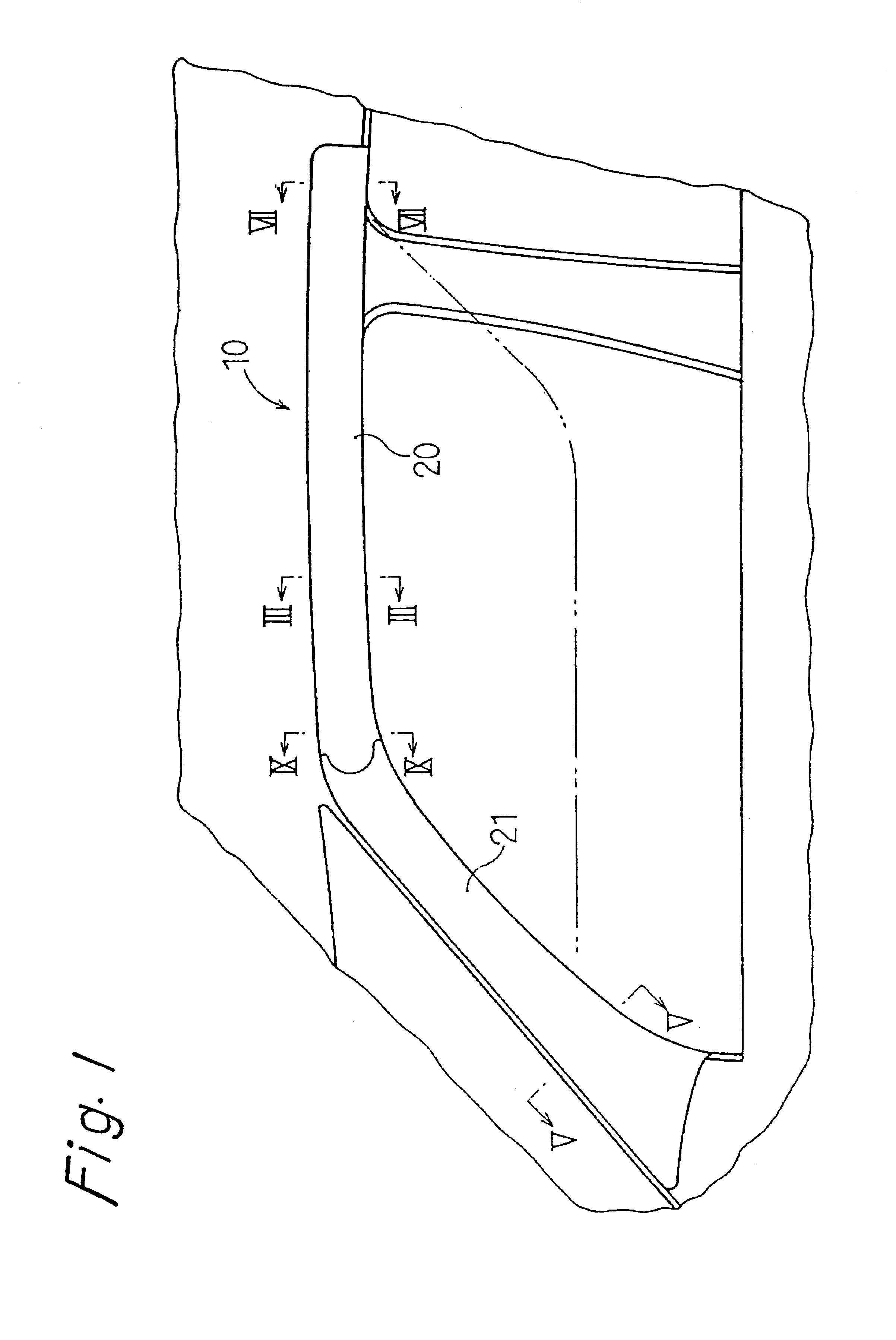
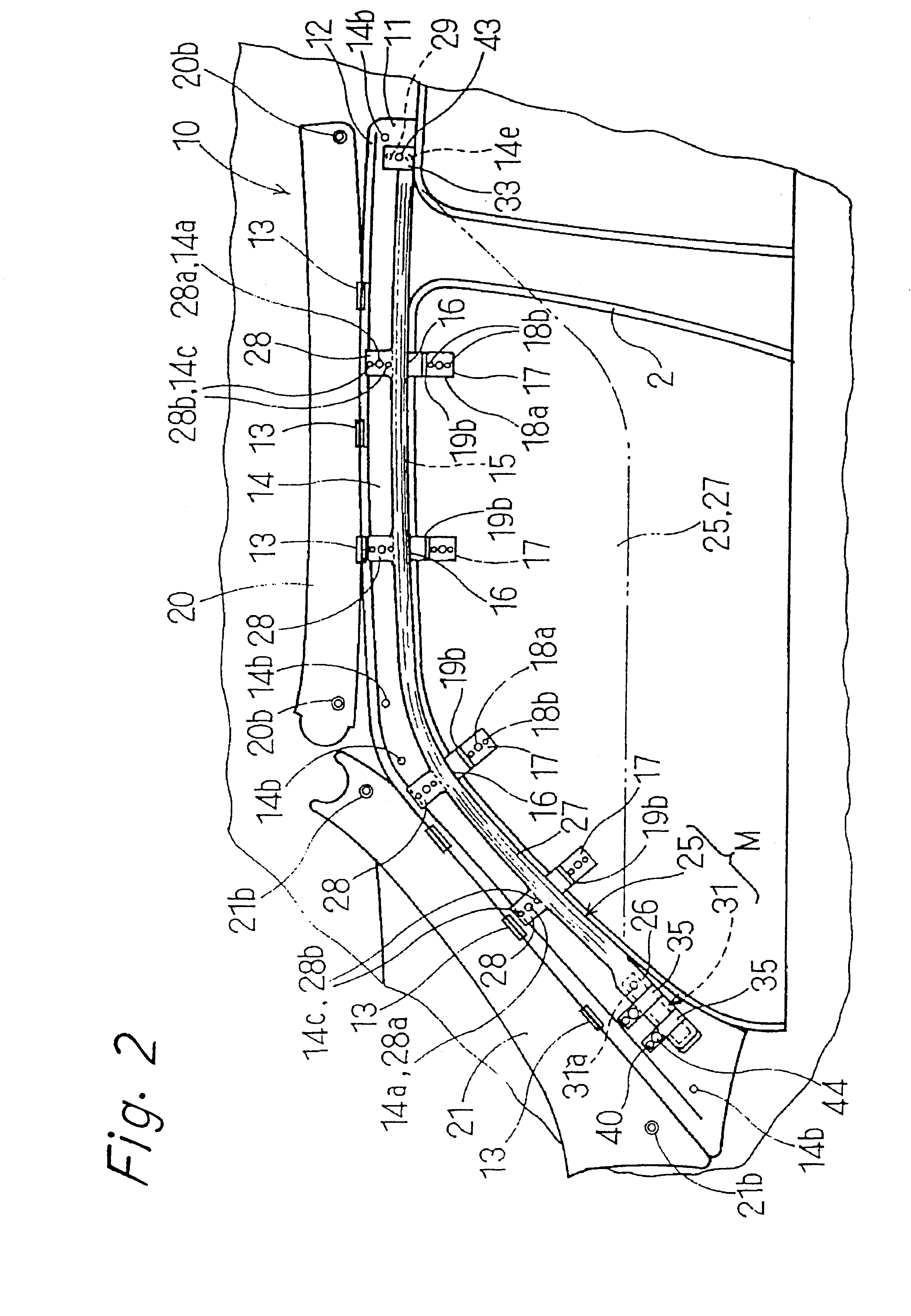
As shown in FIGS. 1 and 2, garnish members 10 according to the present invention are disposed in a section from a front pillar to a roof side rail on a circumference of a door opening inside of a vehicle body. The garnish members 10 contain an air bag apparatus M. The air bag apparatus comprises an air bag 25 and an inflator 31 for supplying inflation gas to the air bag 25.

The air bag 25 comprises a cylindrical portion 26 and a bag body 27. The cylindrical portion 26 is a cylinder having a closed bottom. The bag body 27 is formed so as to be inflated in a diamond-shaped fashion. The cylindrical portion 26 forms a portion connecting with the inflator 31. The cylindrical portion 26 is constructed so as to surround the inflator 31 according to this embodiment.

As shown in FIGS. 2, 7, and 8, a generally rectangular-shaped mounting piece 29 is formed at an end of the bag body 27. The mounting piece 29 has a mounting hole 29a in the center thereof and two fixing holes 29b located around th...

second embodiment

the present invention indicates such an embodiment in which the inflator 31 and the cylindrical portion 26 of the air bag 25 are temporarily fixed to the fixing portions 65. However, it is permissible to eliminate the fixing portion 65, fit the two clamps to the cylindrical portion 26, and fix the clamps 35, 35 directly onto the body 1 by utilizing the two bolts 44. In this case, the air bag cylindrical portion 26 and the inflator 31 are temporarily fixed to only the respective fixing portions 51 via the bag body 27 of the air bag 25 temporarily fixed to the respective fixing portions 51. Even with such a construction, the same action and effect as those already described can be attained.

Then, the same construction may be applied to the first embodiment. That is, it is permissible to eliminate the fixing portion 11, fit the two clamps 35 to the cylindrical portion 26, and fix the clamps 35, 35 directly onto the body 1 by utilizing the two bolts 44. In this case, the air bag cylindri...


PUM


Abstract

Garnish members according to this invention are installed and fixed to peripheries of a door opening in the interior of a vehicle body. The garnish members have an air bag therein and include elongate garnish bodies disposed in the interior of a vehicle body fixing portions. The fixing portions are hinged to the garnish bodies at a rear side of the garnish bodies and can be fixed to the body. The fixing portions include brackets capable of maintaining folding conditions of the air bag, which brackets can be ruptured when the air bag is inflated.

Description

BACKGROUND OF THE INVENTION1. Field of the InventionThis invention relates to garnish members having an air bag. The garnish members are installed and fixed to peripheries of a door opening in the interior of a vehicle body.2. Description of Related Art Conventionally, a technology described in Japanese Patent Publication No. Hei 6-227340 (see FIGS. 1, 2, 3 of that document) has been well known as a technology in which an air bag apparatus is disposed at a position in the interior of a vehicle body where garnish members are disposed.According to the above construction, an air bag and an inflator of the air bag apparatus are installed and fixed to a vehicle body successively together with the garnish members. Thus, it takes much time and trouble to install the air bag and the garnish members to the body at a position in which the garnish members are disposed.SUMMARY OF THE INVENTIONAn object of the present invention is to solve the above described problem and provide garnish members ...

Claims


Application Information

Patent Timeline
IPC IPC(8): B60R21/20B60R21/201B60R21/213B60R21/215
CPCB60R21/201B60R21/213B60R21/215
Inventor SHIBATA, MINORUKATAGIRI, KATSUHIRONAGANO, AKIYOSHITSUGE, HIROKITANASE, TOSHINORI
Owner TOYODA GOSEI CO LTD
Learn More