Interpolation method and color correction method using interpolation

Inactive Publication Date: 2002-12-24
IMAO KAORU +1
View PDF7 Cites 14 Cited by
  • Summary
  • Abstract
  • Description
  • Claims
  • Application Information

AI Technical Summary

Benefits of technology

Accordingly, it is a general object of the present invention to provide an improved interpolation and color correction method in which the above described problems of the conventional methods are eliminated.
A further object of the present invention is to provide a color correction method which improves the quality of a reproduced image corresponding to a peripheral area of RGB space.
The above mentioned objects of the present invention can be achieved by an interpolation method for converting input color signals into correction signals, which comprises the steps of selecting a triangular prism based x, y and z coordinates of the input signals from plural unit triangular prisms into which XYZ space is divided, reading out lattice point data of the selected triangular prism from a memory in which predetermined correction data is stored, the correction data corresponding to lattice points of each of the plural unit triangular prisms, and calculating correction data corresponding to the input signals through interpolation of values of the lattice point data read out from the memory so that the correction signals are generated based on the calculated correction data. According to the present invention, it is possible to realize color correction hardware of simple construction and carry out accurate color correction using a memory of small storage capacity.

Problems solved by technology

Although this linear masking technique is useful and application of the linear masking allows small-size color correction hardware to be designed, it is difficult to achieve accurate color correction when the linear masking technique is applied, because the ink quantity signals are very roughly defined in formula (1).
This first method has a problem in that it requires a long processing time for color correction and relatively complicated hardware.
Also, in the case of the first method there is a problem in that on boundaries between adjacent unit cubes there exists a discontinuity in interpolation values calculated by the linear interpolation procedure.
Although the second method can be carried out by using a calculation formula which is simpler than that of the first method using 8-point interpolation, there is a problem in that hardware to which the second method is applied must have a relatively great size because of a relatively large number of multipliers required for calculating the color correction values.
Although hardware for carrying out the third method uses only three multipliers and three adders, and the required hardware is of simple construction, there is a problem in that all the bits of data of input RGB signals are input to the multipliers, and the multipliers must have relatively great size.
If the number of small tetrahedrons is not great enough, it is difficult to achieve accurate color correction through the above interpolation techniques.
When approximate Y, M and C ink quantity signals are obtained by the non-linear function being applied to the whole of RGB space using the concentration data from the color patterns, there is a problem in that an excessively large amount of data is generated and in that divergence may occur with respect to lattice points, in the peripheral areas of RGB space, where the concentration data exists sparsely.
In such a case, if Y, M and C ink quantities are preset with respect to lattice points in the peripheral areas as in the above conventional methods, there is a problem in that an irregularly corrected or unusual color may appear in the reproduced image.
Such concentration difference, however, is not always lower than a prescribed level in local areas such as achromatic color areas or highlighted areas where a difference between original color and reproduced color is especially appreciable.
Thus, there is a problem in that the conventional methods do not necessarily provide high-quality reproduced images.

Method used


Image

  • Interpolation method and color correction method using interpolation
  • Interpolation method and color correction method using interpolation
  • Interpolation method and color correction method using interpolation

Examples


second embodiment

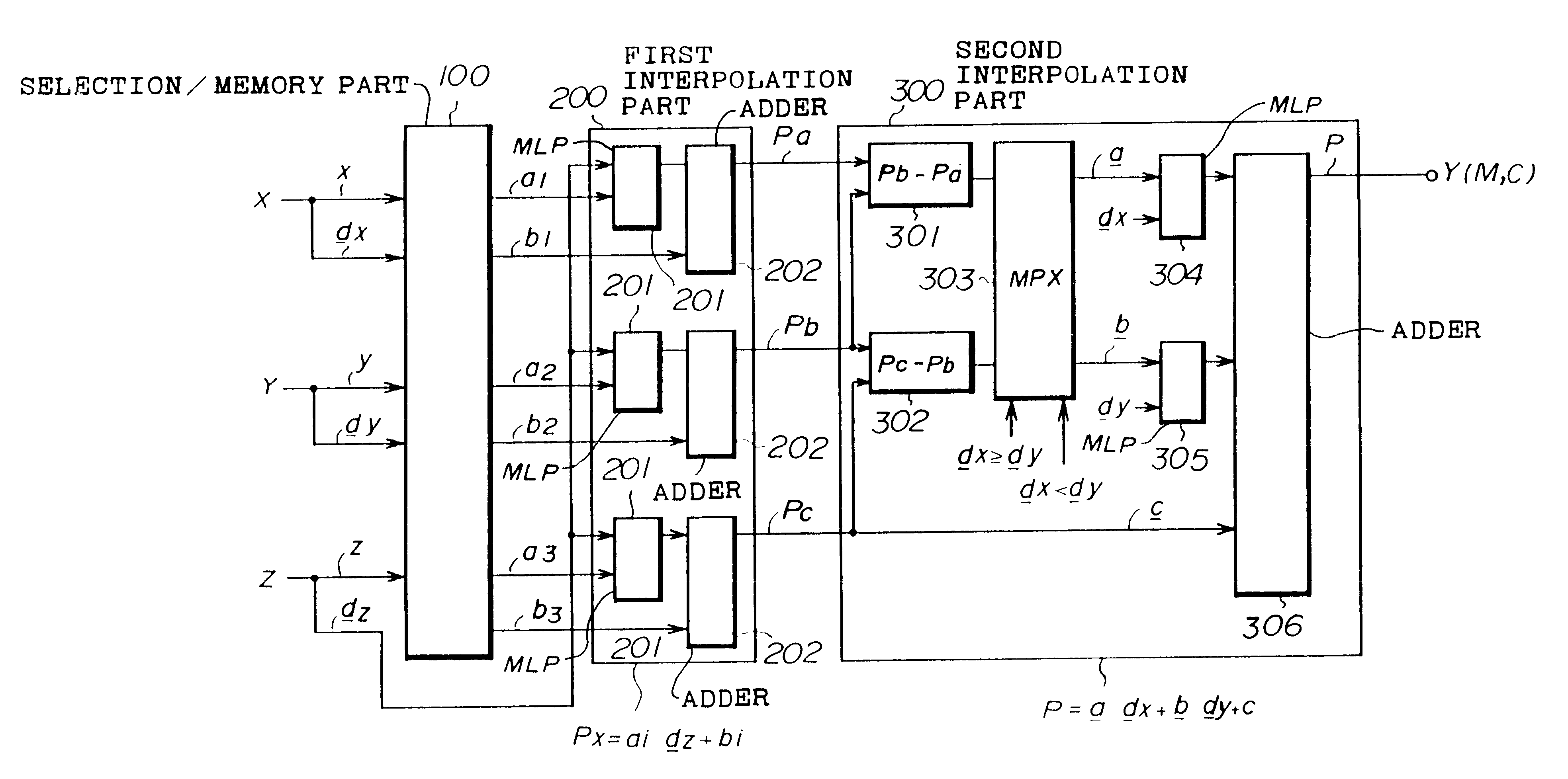
Next, a description will be given of a lo color correction apparatus in the present invention, with reference to FIG.15. In FIG.15, this color correction apparatus includes a read-only memory (ROM) 131, an interpolation part 132 having a random access memory (RAM) 133, a Y signal part 134, an M signal part 135 and a C signal part 136, and a central processing unit (CPU) 137. In the ROM 131, predetermined output data corresponding to lattice points in a triangular prism is stored. For example, when input signals X, Y and Z are divided into four parts, the output data stored in the ROM 131 has a storage capacity equivalent to 64 bytes per color signal. The interpolation part 132 having a construction like that of the first interpolation part 200 or the second interpolation part 300 shown in FIG.3 loads the predetermined lattice point data corresponding to the lattice points, stored in the ROM 131, into the RAM 133 when color correction is started. By making reference to the data loade...

third embodiment

FIG.16 shows a color correction apparatus is the present invention. In FIG.16, this color correction apparatus has a construction that is essentially the same as the second embodiment described above, except that the color correction apparatus shown in FIG.16 includes a picture processing part 138 For example, this picture processing part 130 performs color correction or adjustment of the lattice point data stored in the ROM 131, thereby allowing the color correction apparatus of the third embodiment to perform color correction flexibility.

Next, a description will be given of a color correction apparatus in a fourth embodiment of the present invention. In the above mentioned embodiments, lattice point data Pi (i=1 to 6) corresponding to lattice points of a triangular prism are predetermined. However, in this fourth embodiment, a setting method to predetermine output data corresponding to lattice points of a triangular prism is used for interpolation, and this setting method can be u...

fifth embodiment

A detailed description will be given of a setting method to preset output data corresponding to eight lattice points of a triangular prism, which is used for the interpolation method in this fifth embodiment of the invention. In the color copier shown in FIG.18, density data (R, G, B) for the color pattern data is measured from Y, M and C color signals supplied by the color correction circuit 164 before the UCR process is performed. The Y, M and C color signals include 4913 (=17.sup.3) data which are obtained by dividing halftone levels of color signals (Y, M, C) (each having bits indicating 256 halftone levels) in 16 stages, as follows. Y: 0, 15, 31,..., 239, 255 M: 0, 15, 31,..., 239, 255 C: 0, 15, 31,..., 239, 255

FIG.19 shows an example of output data which are obtained by scanning the 4913 color pattern data (color patch data) and measuring the results of color correction performed by the color copier shown in FIG.18. The output data is used as the predetermined color correction...


PUM


Abstract

An interpolation method for color correction generates correction signals Y, M and C from input signals R, G and B through interpolation. In this interpolation method, a triangular prism is selected from plural unit triangular prisms in RGB space, based on x, y and z coordinates of the input signals, a gradient factor and an intercept factor of the selected prism are read out from a memory, and correction data corresponding to the input signals is calculated through interpolation using the gradient and intercept factors from the memory, so that the correction signals are generated based on the calculated correction data.

Description

BACKGROUND OF THE INVENTIONThe present invention generally relates to an interpolation method and a color correction method using interpolation, and more particularly to an interpolation method and a color correction method using interpolation in which yellow, magenta and cyan signals are generated from red, green and blue input signals. The methods are applicable to color copiers and color facsimile machines.A linear masking techniques is known as a conventional color correction method. In this linear masking method, yellow, magenta and cyan ink quantity signals Y, M and C are obtained from red, green and blue input concentration signals R, G and B, and a relationship between the ink quantity signals and the input signals is represented by the following formula.In the formula (1), a10 through a33 are correction coefficients whose values can be determined through a beast square method on measurement data obtained by scanning several color pattern data.Although this linear masking te...

Claims


Application Information

Patent Timeline
IPC IPC(8): H04N1/60G03G15/01G06F17/17G06T1/00G06T1/20H04N1/40H04N1/46
CPCH04N1/6019
Inventor IMAO, KAORUOHUCHI, SATOSHI
Owner IMAO KAORU
Why Eureka
Try Eureka