
Desiccant assisted multi-use air pre-conditioner unit with system heat recovery capability

Inactive Publication Date: 2001-12-11
DESIGN BUILD SYST
View PDF20 Cites 53 Cited by
  • Summary
  • Abstract
  • Description
  • Claims
  • Application Information

AI Technical Summary

Benefits of technology

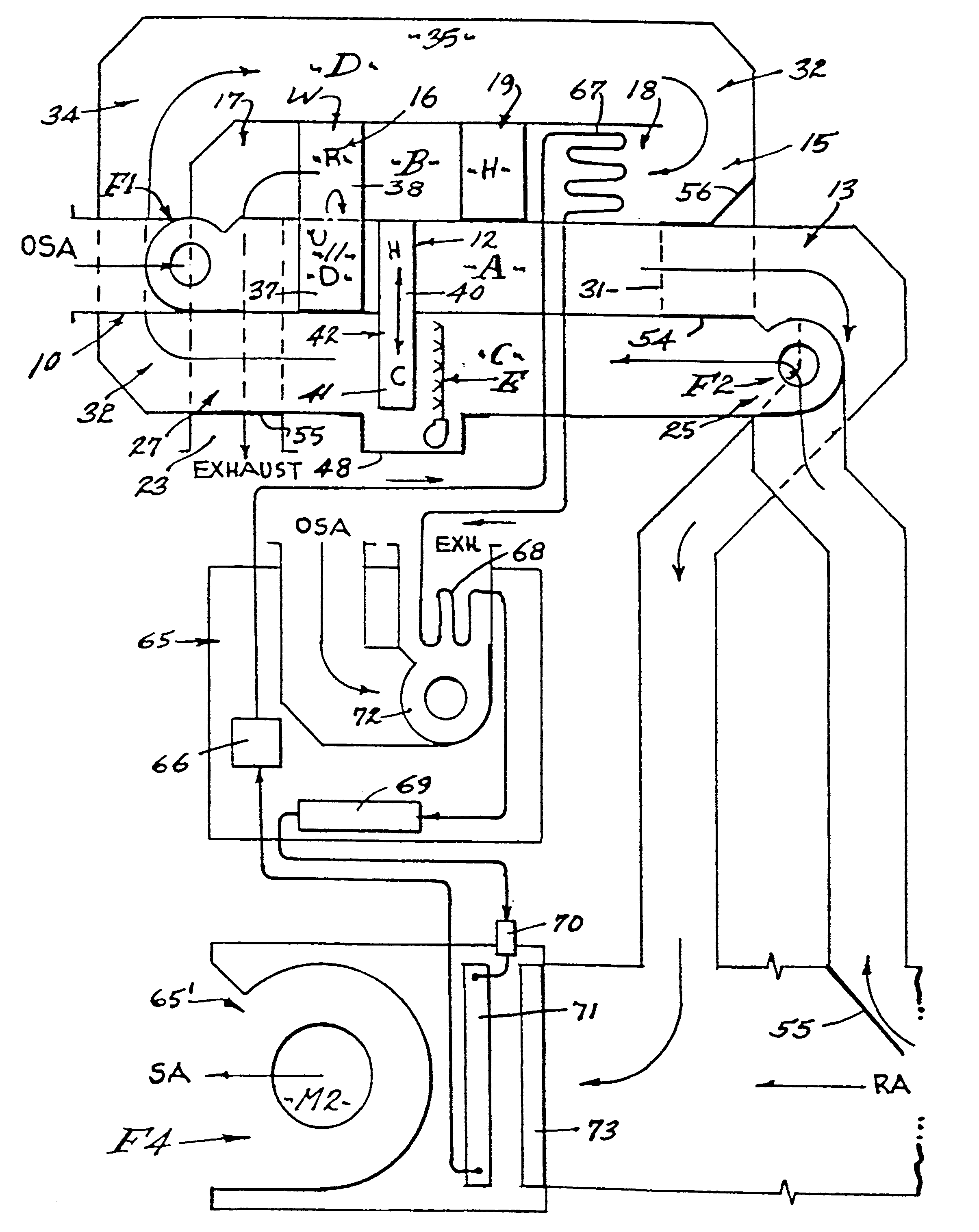
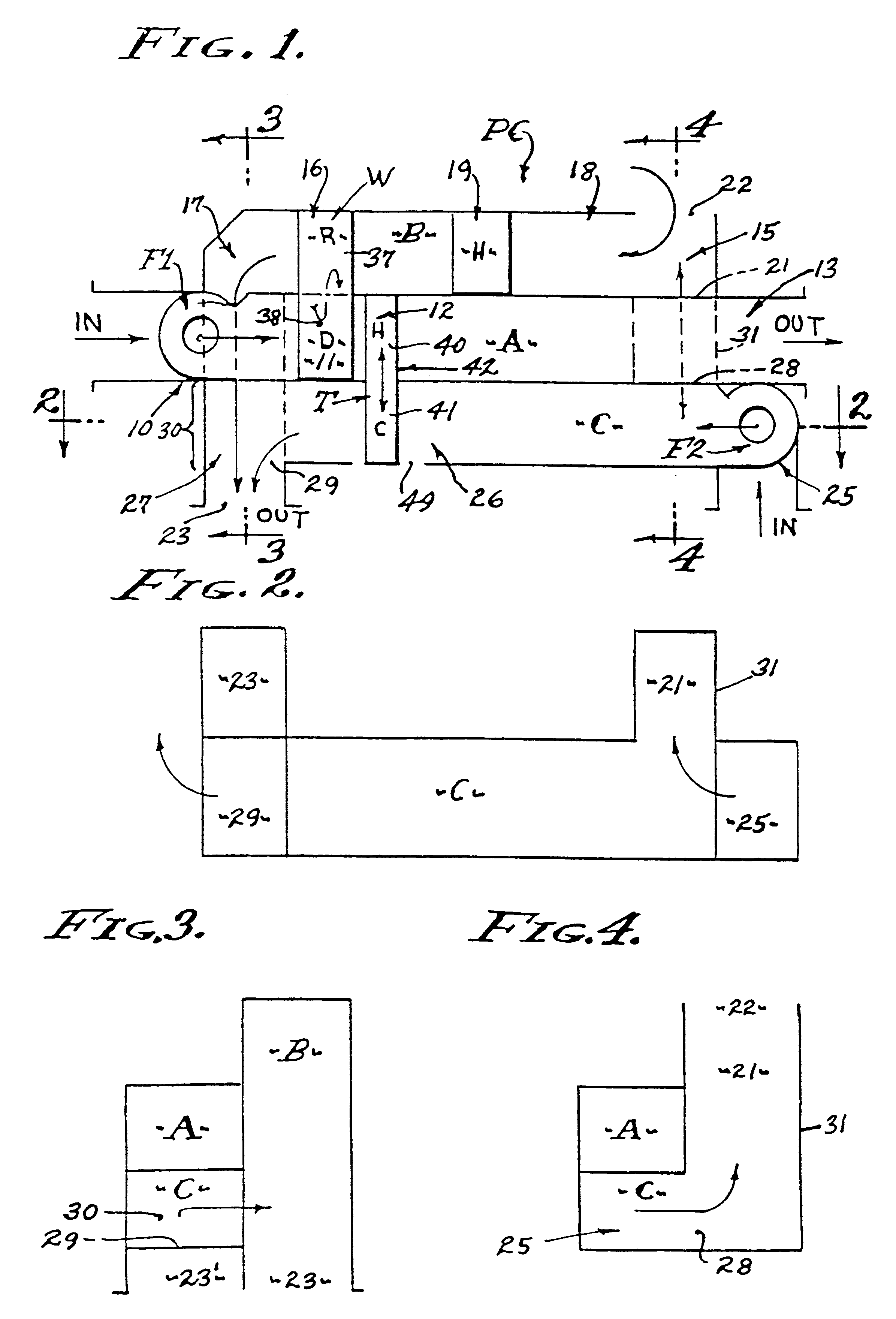
The inventive concept herein disclosed provides a versatile air pre-conditioner that is adapted to be implemented in various configurations as a stand-alone unit, in that it is self sufficient, if need be, to humidify or dehumidify incoming air. Outside air and / or return air from conditioned space is processed, with or without refrigeration, to be dehumidified in hot-wet climate, and humidified in cold-dry climate conditions. The structural configuration of this air pre-conditioner can vary widely, as to size, shape and disposition of the ducting means therein, and characterized by two dedicated ducting means, and at least one additional ducting means that processes waste heat from the desiccant dehumification process employed therein, the quantity of said waste heat being adequate but lacking in temperature. Accordingly, a supplemental heater means is provided to furnish the difference for effective regeneration of weakened desiccant. The need for supplemental heat is greatly reduced when this air pre-conditioner is combined with a refrigeration system wherein substantial amount of heat is available from the waste heat of compression. To this end, a maximum amount of heat is taken from the condenser circuit of the refrigeration system, by placing a second condenser coil in parallel or preferably in series therewith, the advantage of which has been described.

Problems solved by technology

Humidity has its effect upon building construction, as high humidity reduces the presence of mold and mildew, and can be controlled to levels which contribute to the elimination of bacteria propagating environments, For example, refrigeration air conditioner systems in humid environments are often inadequate with respect to acceptable humidity control, with or without refrigeration incorporated therein.
And, in wet environments refrigeration air conditioner systems utilizing refrigerant cooled air coils are often overtaxed and their efficiency adversely affected.

Method used


Image

  • Desiccant assisted multi-use air pre-conditioner unit with system heat recovery capability
  • Desiccant assisted multi-use air pre-conditioner unit with system heat recovery capability
  • Desiccant assisted multi-use air pre-conditioner unit with system heat recovery capability

Examples


Embodiment Construction

This invention relates to a versatile multi-use stand-alone dehumidifier unit adapted to pre-condition air in conjunction with, but not necessarily with refrigeration systems, whereby optimum humidity is attained in differing climatic conditions, waste heat being used when available for efficiency in the operation of both the dehumidification means and the refrigeration air conditioning means when combined therewith. Humidity has its effect upon building construction, as high humidity reduces the presence of mold and mildew, and can be controlled to levels which contribute to the elimination of bacteria propagating environments, For example, refrigeration air conditioner systems in humid environments are often inadequate with respect to acceptable humidity control, with or without refrigeration incorporated therein. And, in wet environments refrigeration air conditioner systems utilizing refrigerant cooled air coils are often overtaxed and their efficiency adversely affected. Humidi...


PUM


Abstract

A dehumidifier unit for pre-conditioning air delivered to a multiplicity of separate refrigeration air conditioner units and especially ductless systems where the compressor-condenser unit is separate from the fan-coil unit, and assisted by heat pipe transfer of heat from air dehumidified through a desiccant wheel and by heat of compression from the condenser of one compressor-condenser unit, and with a heater to maintain the temperature of regeneration air through the wheel, one dehumidifier unit pre-conditioning air for a multiplicity of refrigeration air conditioners or fan-coil units.

Description

PREFERRED EMBODIMENTThis invention relates to a versatile multi-use stand-alone dehumidifier unit adapted to pre-condition air in conjunction with, but not necessarily with refrigeration systems, whereby optimum humidity is attained in differing climatic conditions, waste heat being used when available for efficiency in the operation of both the dehumidification means and the refrigeration air conditioning means when combined therewith. Humidity has its effect upon building construction, as high humidity reduces the presence of mold and mildew, and can be controlled to levels which contribute to the elimination of bacteria propagating environments, For example, refrigeration air conditioner systems in humid environments are often inadequate with respect to acceptable humidity control, with or without refrigeration incorporated therein. And, in wet environments refrigeration air conditioner systems utilizing refrigerant cooled air coils are often overtaxed and their efficiency advers...

Claims


Application Information

Patent Timeline
IPC IPC(8): F24F3/14F24F5/00F24F12/00F24F3/12F28D15/04F24F1/00F24F3/00F24F3/06F24F3/147
CPCF24F3/06F24F3/1423F24F5/001F24F12/003F28D15/04F24F3/1411Y02B30/563F24F2001/0066F24F2003/005F24F2003/144F24F2003/1458F24F2003/1464F24F2012/005F24F2203/102F24F2203/1028F24F2203/1032F24F2203/1036F24F2203/1056F24F2203/1068F24F2203/1084F24F2221/56Y02B30/52F24F1/00075Y02B30/56
Inventor MECKLER, MILTON
Owner DESIGN BUILD SYST
Learn More