Electroacoustic transducer

a transducer and electroacoustic technology, applied in piezoelectric/electrostrictive transducers, generators/motors, instruments, etc., can solve the problems of large number of parts, large complex assembly, etc., and achieve the reduction of the overall size, the number of required parts, and the effect of simple structur

Inactive Publication Date: 2000-08-22
FOSTER ELECTRIC CO LTD
View PDF6 Cites 3 Cited by
  • Summary
  • Abstract
  • Description
  • Claims
  • Application Information

AI Technical Summary

Benefits of technology

According to the electroacoustic transducer embodying this invention, whose outer case is formed integrally with a lead frame previously formed into a predetermined shape, an opening is formed in the outer case, a part of the lead frame is exposed as a pair of lands on the outer surface of the outer case, the coil terminals of the coil are led out of the outer case through the opening to be securely attached to the lands. Unlike the prior art, therefore, this invention needs neither a printed circuit board nor a bobbin at the time of connecting the terminal, thus allowing the number of required parts and the overall size to be reduced, ensuring a simpler structure and facilitating the assembling work.
When a groove is formed in the outer case and the opening and the lands are formed and located in the groove, the terminal disposal section of the coil formed on the lands and the coil lying between the opening and the terminal disposal section of the coil do not protrude from the outer wall of the outer case. Even if the surface of the outer case on which the opening and the lands are formed faces the mounting board of an external unit, such as a portable telephone or a pager, in which the electroacoustic transducer is to be installed, it is unnecessary to provide the mounting board with some means to retain portions protruding from the electroacoustic transducer. Further, as the coil lying between the opening and the terminal disposal section of the coil do not protrude from the outer wall of the outer case, it is possible to prevent the accidental disconnection of the coil. This can ensure the reliability of the product. As the coil terminals are automatically positioned by the groove, no separate positioning means is necessary and the positioning of the coil terminals onto the lands can be accomplished easily and reliably.

Problems solved by technology

The electroacoustic transducers according to the prior art have complicated structures and / or are large, which requires a greater number of parts and involves complicated assembling.
This electroacoustic transducer needs planar space on the side portion of the drive section and thus becomes large.
This inevitably increases the number of required components, complicates the structure and increases the overall size.

Method used


Image

  • Electroacoustic transducer
  • Electroacoustic transducer
  • Electroacoustic transducer

Examples


first embodiment

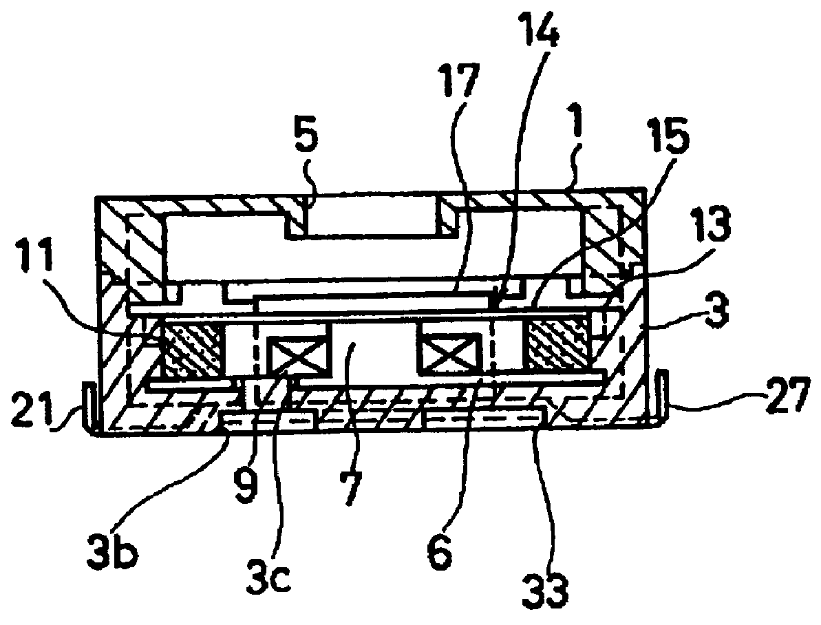
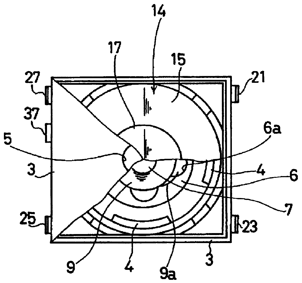
The first embodiment of the present invention will now be described with reference to FIGS. 1 through 7. To begin with, the structure of an electromagnetic type electroacoustic transducer according to this embodiment will be discussed referring to FIGS. 1 to 4. As shown in FIGS. 2 and 3, there are an upper case 1 and a lower case 3, with a circular sound port 5 formed in the center of the top face of the upper case 1 in FIG. 2. A base 6 and a core 7 are arranged at the center portion in the lower case 3 in a securely integrated manner, and a coil 9 is wound around the core 7. A magnet 11 is placed around the coil 9 at the inner wall of the lower case 3. As shown in FIG. 3, the magnet 11 is supported at its outer periphery by four support portions 4 (see FIG. 3) protrusively provided on the inner wall of the lower case 3. Formed on the inner wall of the lower case 3 is a step portion 13 at which a diaphragm 14 is provided, as shown in FIGS. 2 and 3. This diaphragm 14 comprises an ela...

case 3

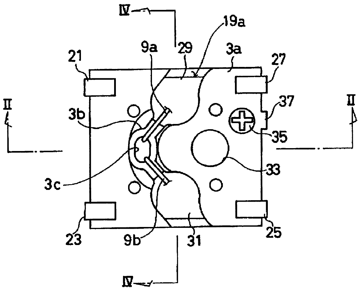
The lower case 3 has the bottom structure as shown in FIG. 1 as seen from the bottom side. The lower case 3 has a bottom wall 3a in which a groove 3b is formed. An opening 3c is formed in the center portion of this groove 3b.

An opening 6a (shown in FIG. 3) is likewise formed in the base 6 located on the inner side of the bottom wall 3a, and the opening 3c is formed at the position matching with the opening 6a.

The groove 3b obliquely extends nearly symmetrically in the up-and-down direction with the opening 3c at the center in FIG. 1. A part of a lead frame element 19a of a lead frame 19 shown in FIG. 5 is integrally buried in the bottom wall 3a by insertion. The four corner portions of the lead frame element 19a are exposed on the lower case 3 as external connection terminals 21, 23, 25 and 27. Some other parts of the lead frame element 19a are exposed in the groove 3b as lands 29 and 31.

Both coil terminals 9a and 9b of the coil 9 accommodated in the lower case 3 are led out to the ...

second embodiment

Referring to FIG. 8, the second embodiment of this invention will be described below. Although the terminal disposal section of a coil is located at the back of the lower case 3 in the first embodiment, the position is not particularly limited to this location. In the second embodiment, the opening 3c is formed in one side wall of the lower case 3 and a pair of lands 29 and 31 of the lead frame element 19a are exposed with the opening 3c in between.


PUM


Abstract

An electroacoustic transducer, which has a lead frame previously formed into a predetermined shape, an outer case formed integrally with the lead frame and a drive section including a coil arranged inside the outer case, comprises an opening formed in the outer case; lands formed by exposing a part of the lead frame through an outer surface of the outer case; and the coil having coil terminals led out of the outer case through the opening and connected to the lands.

Description

BACKGROUND OF THE INVENTION1. Field of the InventionThe present invention relates to an electroacoustic transducer, and, more particularly, to an electroacoustic transducer, which has an outer case formed integral with a lead frame previously formed into a predetermined shape and has some improvement on the structure of the terminal disposal section of a coil, thereby contributing to the reduction of the number of required parts, the simplification of the structure, the reduction of the size, and improvements on its performance and assembly efficiency.2. Description of the Related ArtA variety of electroacoustic transducers include various types of electromagnetic type electroacoustic transducers. An electromagnetic type electroacoustic transducer as the first prior art is illustrated in FIGS. 11 and 12. There are an upper case 501 and a lower case 503, with a circular sound port 505 formed in the center of the top face of the upper case 501 in FIG. 11. A base 507, a printed circuit...

Claims


Application Information

Patent Timeline
Patent Type & Authority Patents(United States)
IPC IPC(8): H04R13/00G10K9/12G10K9/13
CPCH04R13/00H04R1/06
Inventor TAJIMA, KAZUSHIGEIMAHORI, YOSHIO
Owner FOSTER ELECTRIC CO LTD
Why Eureka
Try Eureka