
Optical transmitter with a heat dissipation structure

a technology of optical transmitter and heat dissipation structure, which is applied in the direction of semiconductor lasers, laser details, electrical apparatus, etc., can solve the problems of increasing the number of chips, reducing the efficiency of transmitting voluminous data, and limiting the bandwidth and transmission speed of conventional cable-based telecommunication transmission, so as to improve the efficiency of heat dissipation, shorten the heat conduction path, and influence the efficiency of dissipating heat from the laser dio

Active Publication Date: 2018-06-05
LUXNET CORP
View PDF4 Cites 0 Cited by
  • Summary
  • Abstract
  • Description
  • Claims
  • Application Information

AI Technical Summary

Benefits of technology

This patent is about an optical transmitter with a heat dissipation structure. The invention includes a circuit substrate with an adhesive applied to prevent heat from returning to the laser diode through the electrical connection wires. Additionally, the invention includes a heat dissipation well and a direct heat conduction path from the laser diode to the heat dissipation substrate. The technical effects of this invention include improved heat dissipation efficiency and reduced temperature control with better stability and reliability.

Problems solved by technology

Due to the ever-increasing processing speed and processing capacity of computers, conventional cable-based telecommunication transmission is so restricted by bandwidth and transmission speed that it is no longer effective in transmitting the voluminous data to be processed at any time to meet technological needs nowadays.
However, an enormous increase in power leads to an increase in the number of chips of a light emission module required in the course of signal transmission to meet the need for an increasingly large load of processing and operation, thereby generating lots of heat with high temperature.
In high-temperature surroundings, signal transmission carried out with an optical fiber is unstable, and thus an optical fiber transmission system or equipment thereof ends up in a vicious cycle of an ever-increasing ambient temperature; eventually, the optical fiber transmission speed becomes low and even it jeopardizes the chips or related parts and components.
In the worst-case scenario, the whole optical fiber transmission system or its equipment gets damaged and thus become unusable.

Method used


Image

  • Optical transmitter with a heat dissipation structure
  • Optical transmitter with a heat dissipation structure
  • Optical transmitter with a heat dissipation structure

Examples


Embodiment Construction

[0042]In the following detailed description, for the purpose of explanation, numerous specific details are set forth in order to provide a thorough understanding of the disclosed embodiments. The scale of the figures may not be drawn in its actual proportion but may be exaggerated for the convenience of illustration. The figures and its scale are not restrictive to the present invention.

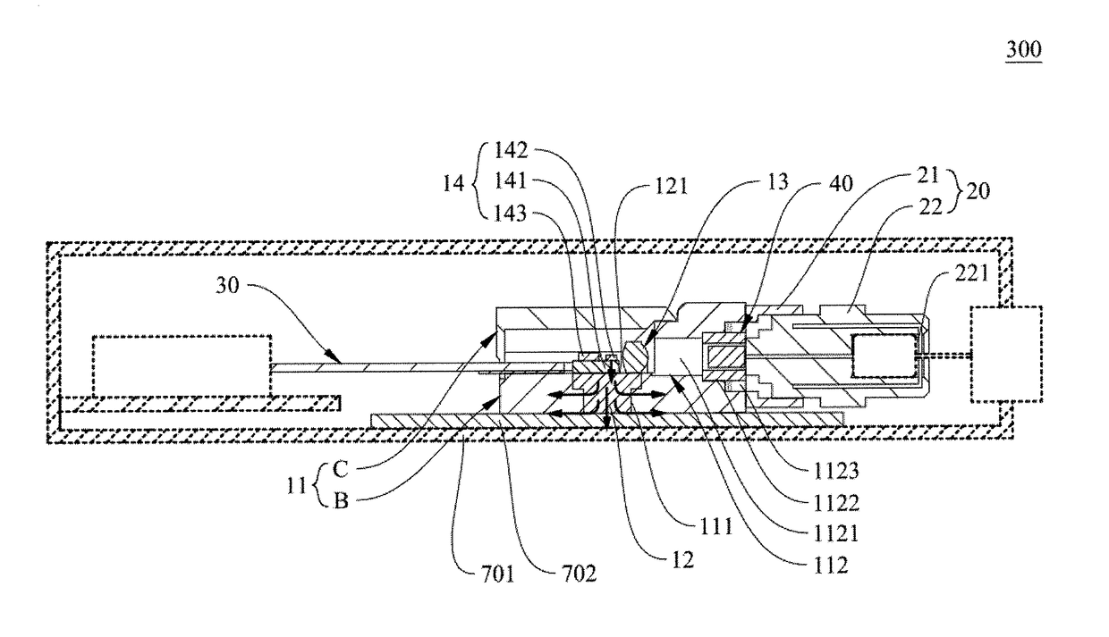
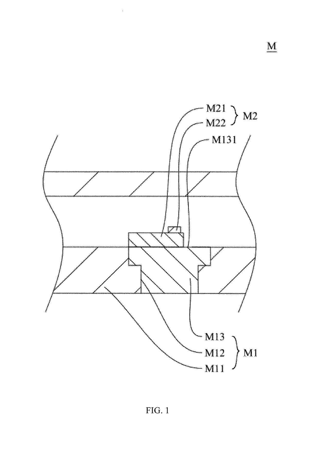
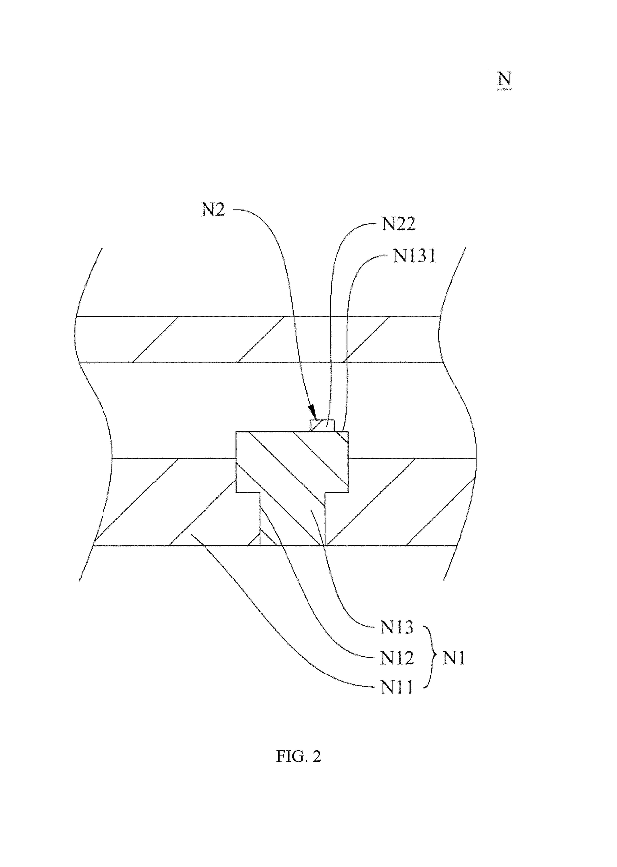
[0043]An optical transmitter with a heat dissipation structure of the present invention is hereunder described with reference to drawings. Referring to FIG. 1, there is shown a schematic view of a heat dissipation structure of optical transmitter according to a preferred embodiment of the present invention, and the diagram illustrates the present invention hereunder.

[0044]A heat dissipation structure M of optical transmitter of the present invention comprises a substrate M1 and an optical transmitter unit M2 disposed on the substrate M1. The substrate M1 comprises a base body M11, a heat dissipation ...


PUM


Abstract

An optical transmitter with a heat dissipation structure is provided. The heat dissipation structure comprises a substrate and an optical transmitter unit. The substrate comprises a base body, a heat dissipation well disposed on the base body, and a thermal conductive block inserted into and fixed to the heat dissipation well. The thermal conductive block has on one side thereof a heat guiding plane. The optical transmitter unit comprises a heat dissipating substrate directly disposed on the heat guiding plane, and a laser diode directly disposed on the heat dissipating substrate. The laser diode features an active region whose height is lowered to shorten a heat conduction path wherein heat is transferred from the active region through the heat dissipating substrate to the heat guiding plane. The heat already transferred to the heat guiding plane is transferred horizontally by the thermal conductive block to the base body which encloses the heat dissipation well.

Description

BACKGROUND OF THE INVENTIONField of the Invention[0001]The present invention relates to optical transmitter with a heat dissipation structure and, more particularly, to an optical transmitter with a heat dissipation structure for enhancing efficiency of heat dissipation greatly.Description of the Prior Art[0002]Due to the ever-increasing processing speed and processing capacity of computers, conventional cable-based telecommunication transmission is so restricted by bandwidth and transmission speed that it is no longer effective in transmitting the voluminous data to be processed at any time to meet technological needs nowadays. In view of this, conventional telecommunication transmission systems have been gradually replaced by optical fiber transmission systems. The optical fiber transmission systems advantageously get rid of bandwidth limitations, enable high-speed and long-distance transmission, and are made of materials insusceptible to electromagnetic interference. Therefore, t...

Claims


Application Information

Patent Timeline
Patent Type & Authority Patents(United States)
IPC IPC(8): H01S5/024H01S5/022
CPCH01S5/02469H01S5/02208H01S5/02438H01S5/02288H01S5/02296H01S5/02284H01S5/02492H01S5/0064H01S5/02212H01S5/02276H01S5/02251H01S5/02345H01S5/02253H01S5/02257
Inventor LAW, PI-CHENGHUANG, PO-CHAOLIN, HSING-YENFU, CHUNG-HSINSU, HUA-HSIN
Owner LUXNET CORP
Learn More