
System and method for measuring grain cart weight

a technology of grain carts and weights, applied in the field of weighing dynamic loads, can solve the problems of contaminating the accuracy of the measured payload weight, inaccurate weight measurement, and weight measurement compromise, and achieve the effect of enhancing display location diversity

Active Publication Date: 2018-05-29
BITSTRATA SYST INC
View PDF3 Cites 14 Cited by
  • Summary
  • Abstract
  • Description
  • Claims
  • Application Information

AI Technical Summary

Benefits of technology

The patent text describes two ways to improve the performance of a device that measures weight and acceleration. The first way involves using data from an accelerometer to compensate for uneven or rough terrain. The second way involves reversing the displayed image when unloading and restoring it using a mirror to enhance the device's display location diversity.

Problems solved by technology

However, while conventional methods and technologies have gained significant market acceptance, it has been noted that there are numerous issues with the current state of the art.
While on-board weighing systems can generally provide accurate static measurements on level ground, weight measurements can be compromised by forces that originate either on-cart (auger operation) or from accelerations due to drops and impacts with obstacles on uneven terrain.
The degree of measurement contamination relates to the specific terrain, cart resonances, and vehicle velocity—higher speeds having a more significant adverse impact on accuracy. FIG. 3 is a graph that illustrates the measurement dynamics that may be experienced while traversing a rough field, which contaminate the accuracy of the measured payload weight.
Even while stopped, uneven ground can result in inaccurate weight measurement, since the axis of sensitivity of the weighing sensor becomes misaligned with the gravity vector.
Generally, unloading the cart (loading the truck) is done while stopped or at very low speeds, so dynamics are kept to a minimum allowing high-quality measurement; however, often the critical start and stop phases involve rapid cart acceleration or deceleration to and from the combine for purposes of time efficiency; this usually results in vibrations seen by the weight sensors.
Such dynamics, and those experienced when shuttling across rough terrain, make the ostensibly simple process of automatically recording the weights when they start and stop changing during an unloading or loading process much more difficult.
In fact, the process is sufficiently difficult that some manufacturers avoid monitoring weight for this purpose altogether, and instead monitor the equipment that drives the grain transfer auger in order to gate the unloading process; this of course does not help in determination of the loading process.
Lack of identification of the harvesting equipment (combine and truck) involved in grain transactions limits the usefulness of the collected management information.
Although a grain cart operator could record such information manually, operator error due to the monotony and exhaustion suffered by cart operators leaves manually collected data unreliable.
No telemetric operational coordination currently exists between grain cart and combine.
Over time, these devices can fail by delamination of the internal strain gauges, vibrational stresses harming internal wiring, or by physical damage to the bar or external wiring.
The damage can occur slowly or abruptly depending on the failure mode, but in all cases ultimately affects the weighing performance.
Such remedies can result in weight inaccuracies and erroneous farm management data.
However, there is no automated system or methodology available to detect and isolate this problem.
Although a scale display terminal is useful in both the loading (from combine) and unloading (to truck) phases, a single display cannot be positioned so that it may be viewed practically in both phases because the operator faces in opposing directions due to the relative locations of combine and truck during loading and unloading.
Currently, either two displays are required, which is complicated and costly, or the operator must split his attention between the display and the grain transfer itself, which is error prone and inefficient.

Method used


Image

  • System and method for measuring grain cart weight
  • System and method for measuring grain cart weight
  • System and method for measuring grain cart weight

Examples


Embodiment Construction

[0037]The present invention differs from solutions offered by others as it does not have a monolithic topology, but instead uses a mobile device as the display terminal, user interface, and processing engine, and which connects wirelessly to electronics located on a grain cart. The signals from weight sensors are combined through use of a junction box; the resulting signal is then forwarded to the electronics for measurement, conversion, and transmission to the mobile device. Leveraging mobile devices in the present invention reduces product cost, increases processing capacity, and provides advanced data connectivity and navigational capabilities, while enhancing customer familiarity and thus market acceptance. This topology is shown in FIG. 4.

[0038]Exemplary embodiments of the present invention will now be described with reference to the appended drawings.

[0039]Measurement Dynamics.

[0040]Exemplary embodiments of the present invention can include techniques to assist with achieving ...


PUM


Abstract

A system of detecting loading and unloading of mobile containers such as grain carts utilizes two low pass filters to determine whether the contents of the container are changing by subtracting one filter signal from the other, and using the sign of the difference. Weighing performance is improved by utilizing accelerometers to compensate for measurement dynamics and non-level orientation. Failure and degradation of weight sensors is detected by testing sensor half bridges. Loading and unloading weights can be tied to specific vehicles by utilizing RF beacons.

Description

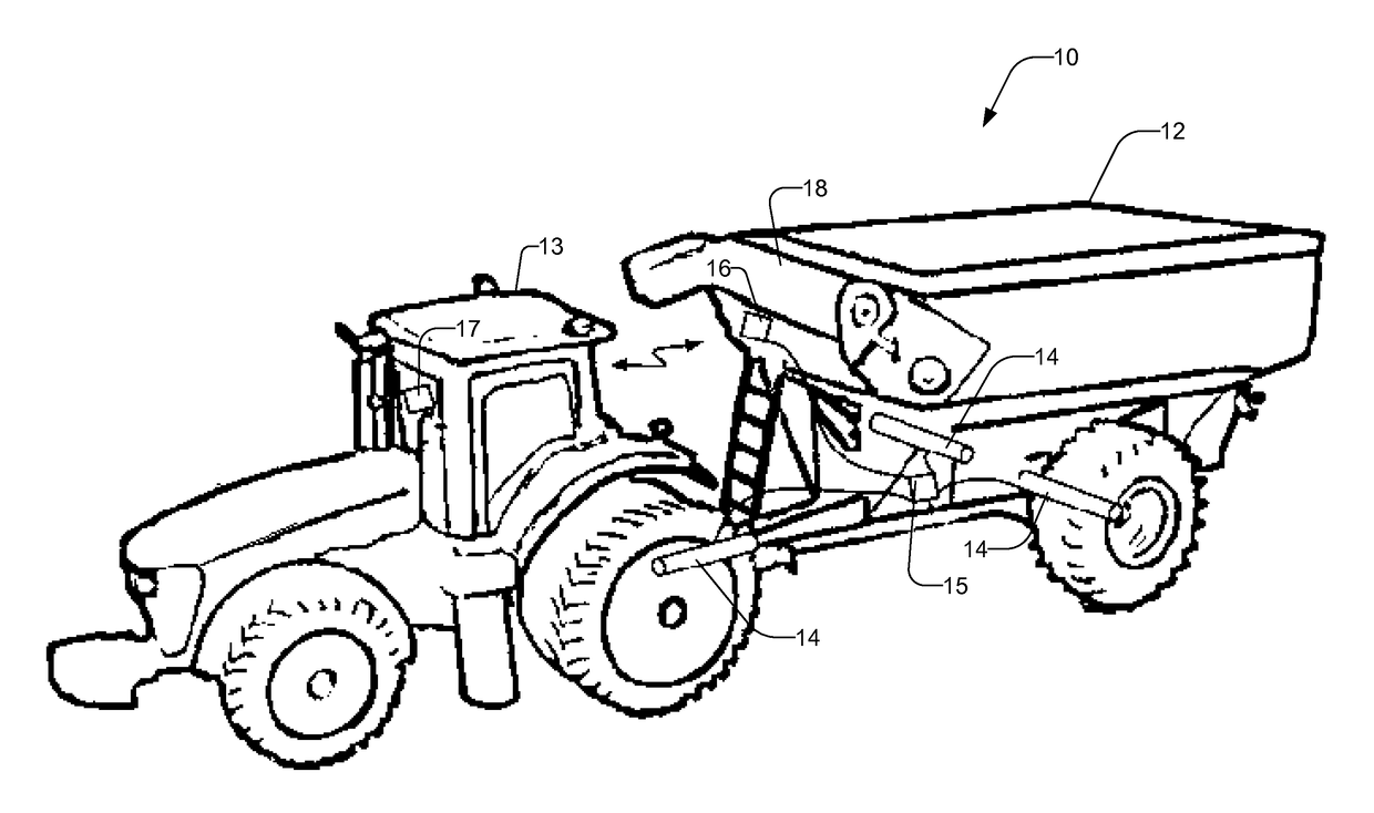
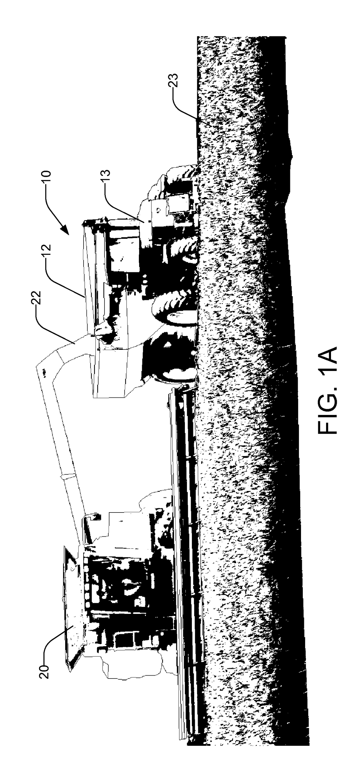
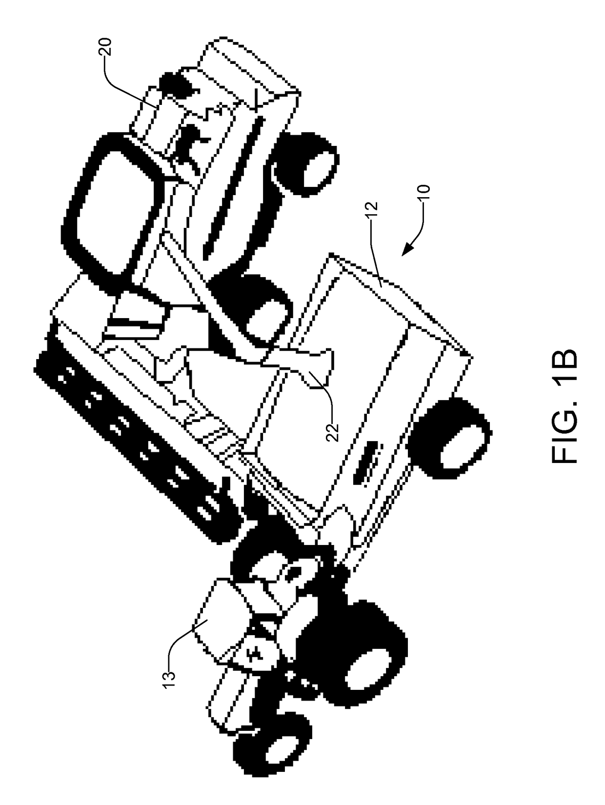
BACKGROUND OF THE INVENTION1. Field of the Invention[0001]The present invention relates to weighing dynamic loads and, more specifically, to apparatus and method for weighing grain cart loads.2. The Prior Art[0002]FIGS. 1A and 1B are drawings that show a combine 20 loading grain 22 from a field of grain 23 into a grain cart 10. FIG. 2 is a drawing showing a grain cart 10 with a grain truck 24. Grain carts 10 are large-capacity pull-type trailers with a container 12 for grain 22, a built-in discharge auger 18, and capacities currently as high as 2,000 bushels. A tractor 13 with grain cart 10 typically shuttles grain 22 from a combine 20 in a field to a grain truck 24 located at the edge of the field. The grain carts 10 are typically loaded by or from a combine 20, and then unloaded into a truck 24, with combines 20 and trucks 24 typically utilized with one or more grain carts 10 to harvest fields of grain. The use of grain carts dramatically increases harvest efficiency, allowing com...

Claims


Application Information

Patent Timeline
IPC IPC(8): G01G19/08G01G15/00G01G19/00G01G13/24G01G13/00G01G19/12G01G23/18
CPCG01G13/24G01G13/006G01G15/00G01G19/00G01G13/28G01G23/10G01G19/08G01G19/12G01G13/00G01G23/18
Inventor MEIER, IAN ROBERTLOCKERBIE, MICHAEL DAVID
Owner BITSTRATA SYST INC
Learn More