
Vehicle accessory microphone

a technology for accessories and microphones, applied in the field of vehicles, can solve the problems of difficult to attenuate noise, detect undesirable noise, and difficult to use hands-free communication systems for vehicles

Inactive Publication Date: 2005-04-19
GENTEX CORP
View PDF105 Cites 53 Cited by
  • Summary
  • Abstract
  • Description
  • Claims
  • Application Information

AI Technical Summary

Benefits of technology

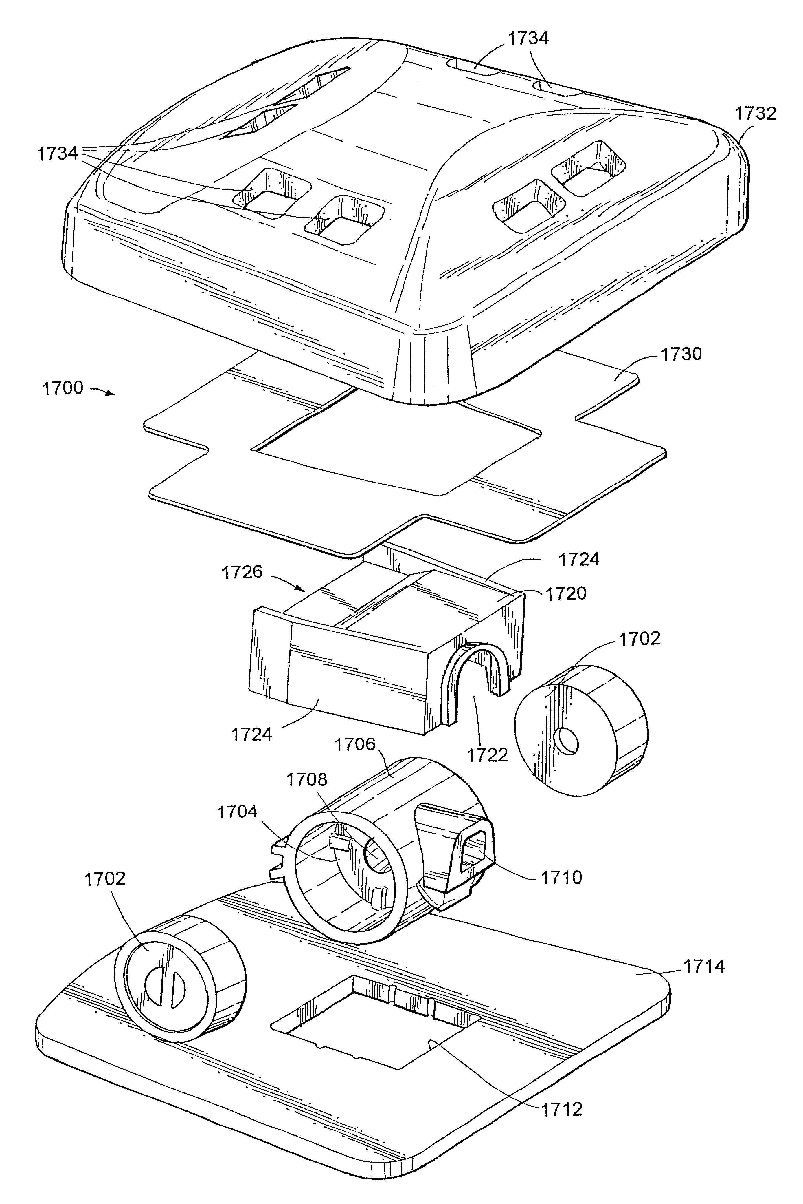
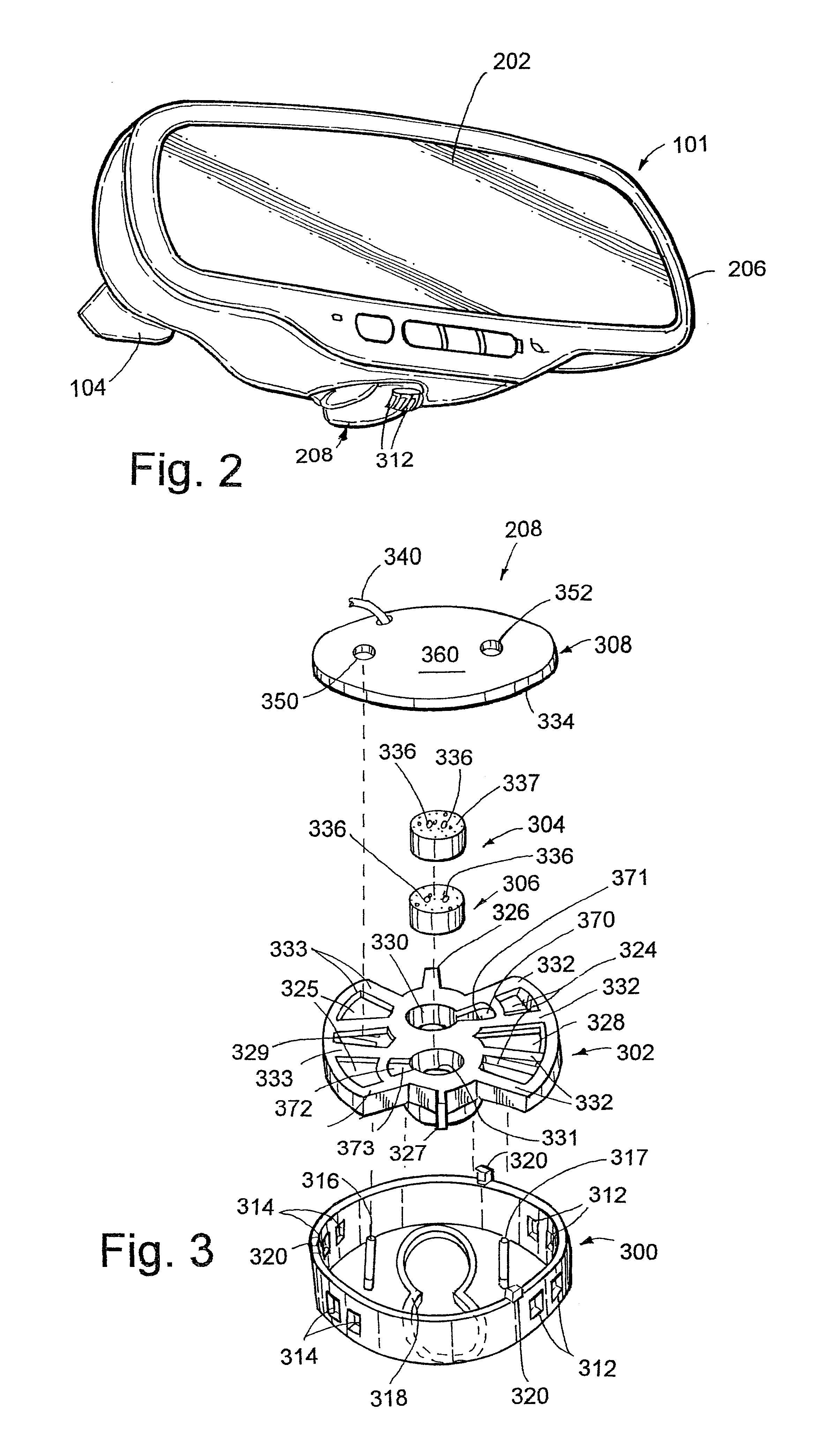
The present invention relates to a microphone system for vehicles that includes a microphone assembly with two transducers and a remote processing circuit. The microphone system has a microphone interface circuit that includes an electrical signal path for each transducer, and a phase inverter circuit for inverting the phase of the second audio signal. The remote processing circuit recognizes the phase inversion and processes the second audio signal accordingly. The invention also includes a housing for attaching the microphone system to the vehicle, a windscreen for the microphone assembly, and a high frequency boost circuit for compensating for the effect of the vehicle on the frequency response of the microphone assembly. The invention also includes a rearview mirror assembly with a microphone housing and multiple transducers to alter the polar pattern and compensate for frequency discrepancies caused by the proximity of the microphone housing to the front surface of the mirror. The technical effects of the invention include improved noise reduction, improved frequency response, and improved vehicle accessory design.

Problems solved by technology

Because of the distance between the user and the microphone, these microphones often detect undesirable noise in addition to the user's speech.
The noise is difficult to attenuate.
Hands-free communication systems for vehicles are particularly challenging due to the dynamically varying ambient noise that is present.
The position of the microphone relative to the person speaking will determine the level of the speech signal output by the microphone and may affect the signal-to-noise ratio.
Additionally, the microphone will typically include a wire, which if it is mounted to the surface of the vehicle interior, will not be aesthetically pleasing.
Alternatively, if the wire is to be mounted behind the interior lining, the vehicle interior must be disassembled and then reattached so that the wire can be hidden, which may result in parts that rattle loudly or hang loosely from the vehicle frame.
Although locating the microphone in the mirror support provides the system designer with a microphone location that is known in advance, and avoids the problems associated with mounting the microphone after the vehicle is manufactured, there are a number of disadvantages to such an arrangement.
Additionally, the location of the microphone on the windshield detrimentally impacts on microphone design flexibility and overall noise performance of the microphone.
None of these patents, however, discloses the use of acoustic ports facing multiple directions nor do they disclose microphone assemblies utilizing more than one microphone transducer.
The disclosed microphone assemblies do not incorporate sufficient noise suppression components to provide output signals with relatively high signal-to-noise ratios, and do not provide a microphone having a directional sensitivity pattern or a main lobe directed forward of the housing and attenuating signals originating from the sides of the housing.
Hands-free operation of a device used in a voice recognition system is a particularly challenging application for microphones, as the accuracy of a voice recognition system is dependent upon the quality of the electrical signal representing the user's speech.
Conventional hands-free microphones are not able to provide the consistency and predictability of microphone performance needed for such an application in a controlled environment such as an office, let alone in an uncontrolled and noisy environment such as an automobile.

Method used


Image

  • Vehicle accessory microphone
  • Vehicle accessory microphone
  • Vehicle accessory microphone

Examples


Embodiment Construction

[0082]The microphone assemblies of the present invention are associated with an interior rearview mirror and have superior performance even in the presence of noise. The microphone assemblies enhance the performance of hands-free devices with which they are associated, including highly sensitive applications such as voice recognition for a telecommunication system, by improving the signal-to-noise ratio of the microphone assembly output. The microphone assemblies eliminate mechanically induced noise and provide the designer with significant freedom with respect to selection of the microphone assembly's sensitivity, frequency response and polar pattern. Additionally, circuitry can be provided for the transducer to generate an audio signal from the transducer output that has a high signal-to-noise ratio.

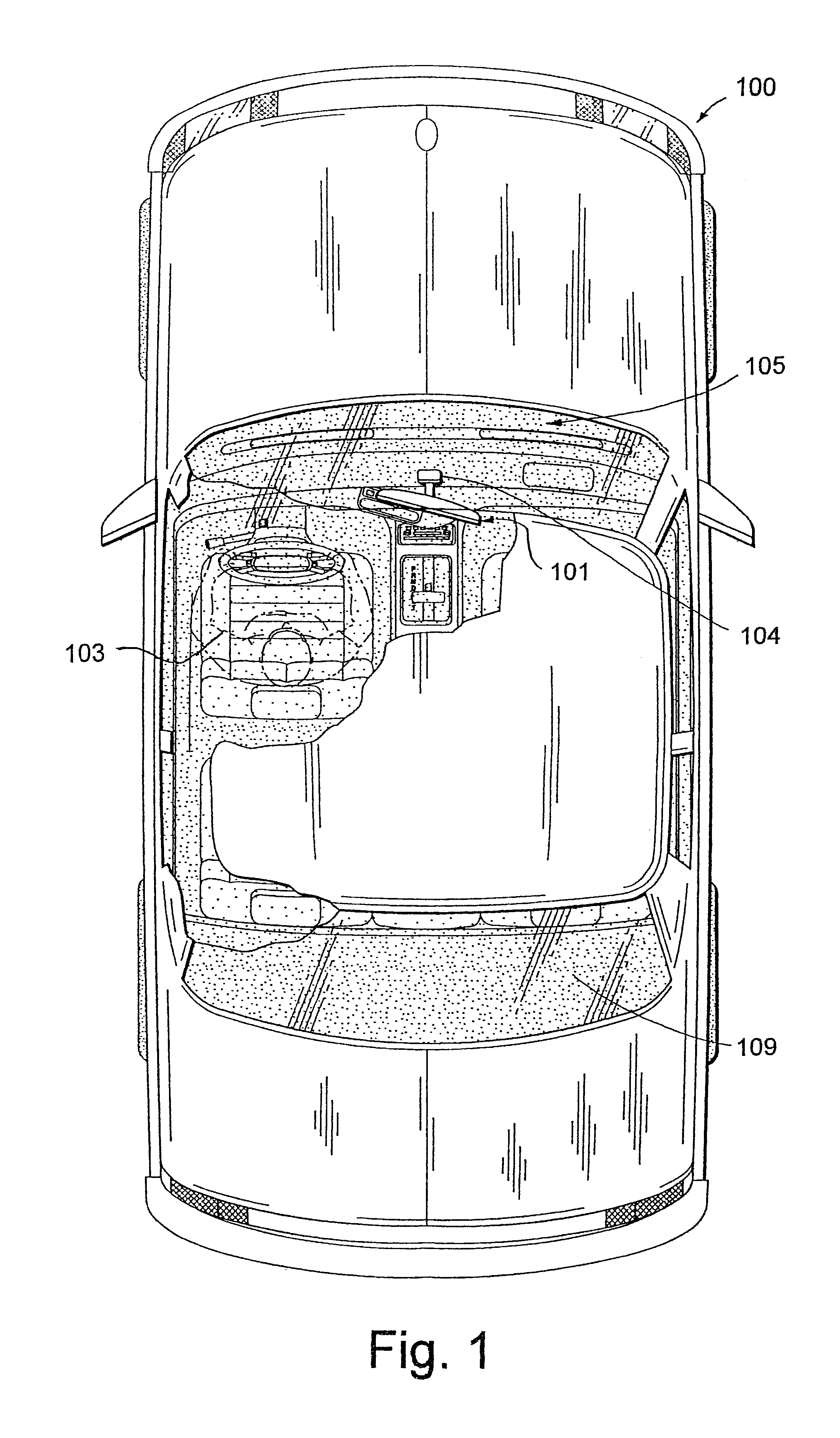
[0083]A vehicle 100 (FIG. 1) includes an interior rearview mirror assembly 101 by which the vehicle operator 103 (illustrated in phantom) can view a portion of the road behind the vehi...


PUM


Abstract

A microphone assembly includes one or more transducers positioned in one or more housings. A processing circuit is coupled to the transducer for outputting an electrical signal such that the microphone in combination with the processing circuit very effectively cancels noise. The microphone assembly can be employed in a vehicle accessory.

Description

CROSS-REFERENCE TO RELATED APPLICATIONS[0001]This application claims priority under 35 U.S.C. §119(e) to the following: U.S. Provisional Patent Application No. 60 / 328,538, entitled “VEHICLE ACCESSORY MICROPHONE,” filed on Oct. 11, 2001 by Alan R. Watson et al.; U.S. Provisional Patent Application No. 60 / 314,252, entitled “VEHICLE ACCESSORY MICROPHONE,” filed on Aug. 22, 2001 by Alan R. Watson et al.; U.S. Provisional Patent Application No. 60 / 285,811 entitled “VEHICLE ACCESSORY MICROPHONE,” filed on Apr. 23, 2001 by Alan R. Watson et al.; U.S. Provisional Patent Application No. 60 / 268,609 entitled “VEHICLE ACCESSORY MICROPHONE,” filed on Feb. 14, 2001 by Alan R. Watson et al.[0002]The disclosures of each of the above-referenced provisional applications are incorporated herein in their entirety.BACKGROUND OF THE INVENTION[0003]The present invention pertains to microphones, and more particularly to a microphone associated with a vehicle accessory such as a rearview mirror assembly or ...

Claims


Application Information

Patent Timeline
Patent Type & Authority Patents(United States)
IPC IPC(8): B60R11/02B60R1/12H04R1/08B60R11/00H04R1/02H04R1/38H04R1/40H04R3/00H04R3/04
CPCB60R1/12B60R11/0247B60R11/0252H04R1/38H04R1/406H04R3/005H04R3/04H04R1/083B60R2001/1284B60R2011/0033H04R2499/13H04R2410/07
Inventor WATSON, ALAN R.BRYSON, MICHAEL A.SPENCE, WILLIAM R.
Owner GENTEX CORP
Learn More