
Method and apparatus for controlling an operating mode of a processing module

Inactive Publication Date: 2018-05-01
NXP USA INC
View PDF18 Cites 0 Cited by
  • Summary
  • Abstract
  • Description
  • Claims
  • Application Information

AI Technical Summary

Benefits of technology

This approach reduces power consumption and minimizes performance impact on timing-critical tasks by automating power mode control, eliminating the need for extensive software customization and detailed application characterization.

Problems solved by technology

Minimising both peak and average power consumption is a significant design consideration for many signal processing applications, and the need to balance performance with reduced power consumption is complicated for multi-core systems with increasing levels of parallelism where the performance demanded from the system can no longer be viewed as a single variable over time.
However, conventional techniques rely on execution of dedicated software to manage low power modes, requiring customisation of software, and introducing latencies in execution of application code.

Method used


Image

  • Method and apparatus for controlling an operating mode of a processing module
  • Method and apparatus for controlling an operating mode of a processing module
  • Method and apparatus for controlling an operating mode of a processing module

Examples


Embodiment Construction

[0013]The present invention will now be described with reference to the accompanying drawings. However, it will be appreciated that the present invention is not limited to the specific examples herein described with reference to the accompanying drawings. For example, the present invention is herein described with reference to a microcontroller unit (MCU), and in particular to an automotive MCU. However, it will be appreciated that the present invention is not limited to being implemented within such an automotive MCU, and it is contemplated that some examples of the present invention may be implemented within alternative signal processing devices such as, by way of example only, microprocessor devices, digital signal processor (DSP) devices, etc.

[0014]Furthermore, because the illustrated embodiments of the present invention may, for the most part, be implemented using electronic components and circuits known to those skilled in the art, details will not be explained in any greater ...


PUM


Abstract

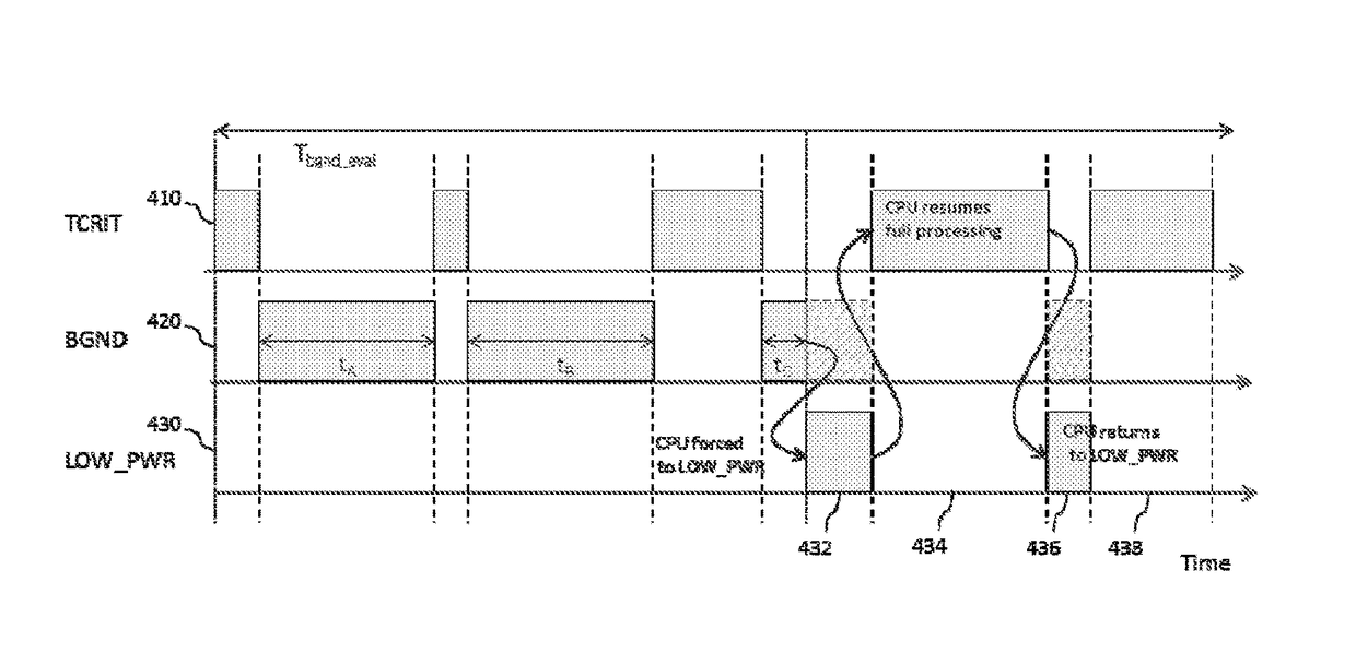
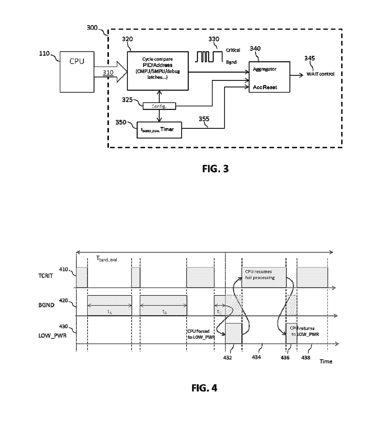
A method of controlling an operating mode of at least one processing module. The method comprises receiving an indication of the execution of at least one background task by the at least one processing module, aggregating an execution duration for the at least one background task on the at least one processing module, and configuring a lower power mode for the at least one processing module when the at least one background task is allocated to the at least one processing module for execution thereon if the aggregated execution duration for the at least one background task exceeds a threshold duration within an evaluation period.

Description

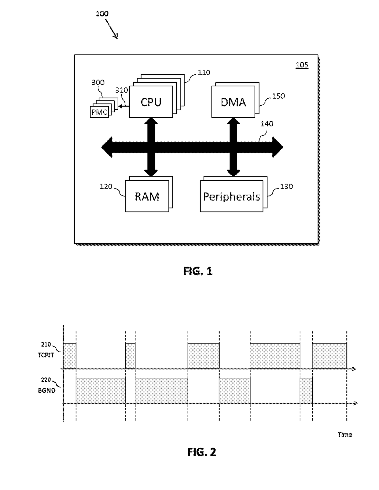
FIELD OF THE INVENTION[0001]This invention relates to a method of controlling an operating mode of a processing module, and a power mode control module therefor.BACKGROUND OF THE INVENTION[0002]Minimising both peak and average power consumption is a significant design consideration for many signal processing applications, and the need to balance performance with reduced power consumption is complicated for multi-core systems with increasing levels of parallelism where the performance demanded from the system can no longer be viewed as a single variable over time. Furthermore, for applications that involve timing-critical processes, power reduction techniques are required to have minimal performance impact on those timing-critical processes.[0003]The use of CPU low power modes is known for reducing power consumption within signal processing applications. However, conventional techniques rely on execution of dedicated software to manage low power modes, requiring customisation of soft...

Claims


Application Information

Patent Timeline
Patent Type & Authority Patents(United States)
IPC IPC(8): G06F1/32G06F13/14G06F9/48G05B15/02
CPCG06F1/329G06F1/3228G06F1/3287G06F1/3293G06F9/4893G06F1/3234G05B15/02G06F13/14Y02D10/171Y02D50/20Y02D10/122Y02D10/24Y02D10/00Y02D30/50
Inventor MAIOLANI, MARKCIRCELLO, JOSEPHMARSHALL, RAY
Owner NXP USA INC
Learn More