
Image reading apparatus

a technology of image reading and reading apparatus, applied in the direction of electrical apparatus, picture communication, etc., can solve the problems of liable power supply, and achieve the effect of suppressing the entry of dust or the lik

Active Publication Date: 2018-04-17
SEIKO EPSON CORP
View PDF17 Cites 0 Cited by
  • Summary
  • Abstract
  • Description
  • Claims
  • Application Information

AI Technical Summary

Benefits of technology

The technical effects of this patent are to reduce the dimension of the image reading apparatus in the height direction by avoiding the superimposition of the insertion / extraction space for the power cable and the area in which the signal transmission cable deforms following the movement of the medium reading unit, and to prevent dust and other debris from entering the apparatus through the power supply by using a partition wall in the housing to separate the movement area of the medium reading unit and the arrangement region of the power supply. This results in a more efficient and reliable apparatus that can be maintained in a clean condition.

Problems solved by technology

The power supply is liable to become an entry section through which dust and the like enter the apparatus, because of the insertion and extraction of the plug of the power cable.

Method used


Image

  • Image reading apparatus
  • Image reading apparatus
  • Image reading apparatus

Examples


embodiment modification

[0061]1. In the embodiment, the power supply 44 is configured to include a rectifier circuit. However, the power supply 44 may further include a battery.

[0062]2. In the embodiment, the medium reading unit driver 42 is configured to move in the apparatus width direction by a toothed belt 62. Instead, the medium reading unit 30 may be moved with a rack-pinion or the like in place of this configuration.

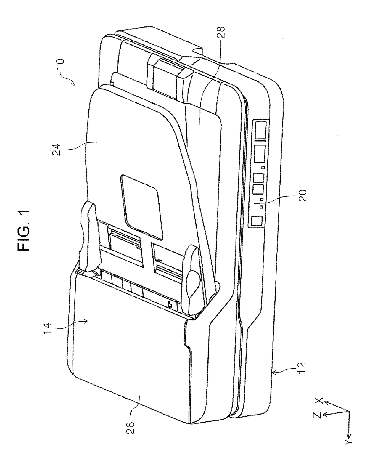
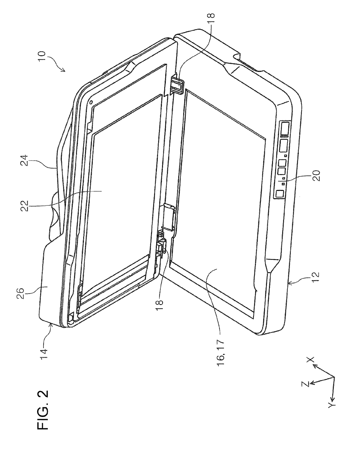
[0063]3. In the embodiment, the image reading apparatus 10 is configured to include the ADF 14. Instead of this configuration, the image reading apparatus 10 may include an open / closeable cover in place of the placement surface 16.

[0064]To summarize the above description, the image reading apparatus 10 includes the medium reading unit 30, the signal transmission cables 66 and 68, the power supply 44, and the housing 12. The medium reading unit 30 reads an image of a medium as the medium moves in the apparatus width direction while extending in the apparatus depth direction. The signal tr...


PUM


Abstract

An image reading apparatus includes a medium reading unit that extends in a main scanning direction and reads an image of a medium while moving in a sub-scanning direction which is a direction crossing the main scanning direction; a signal transmission cable that is a flexible cable having a curved section and connected to the medium reading unit and that deforms following a movement of the medium reading unit; a power supply that supplies power to the medium reading unit; and a housing that accommodates the medium reading unit and the power supply. At least a portion of an insertion / extraction space for inserting / extracting a plug of a power cable from outside the housing to the power supply and at least a portion of an area where the signal transmission cable deforms following the movement of the medium reading unit overlap in a height direction of the medium reading unit.

Description

BACKGROUND[0001]1. Technical Field[0002]The present invention relates to an image reading apparatus such as a scanner.[0003]2. Related Art[0004]An image reading apparatus in which a document is placed on a scanner glass and in which an image reading unit with an image sensor moves below the scanner glass to read an image of the document is known. Such an image reading apparatus is called a flatbed-type scanner, examples of which are disclosed in JP-A-2008-107805 and JP-A-2003-233138. The image sensor has a certain length so as to cover the document width. Generally, the longitudinal direction of the image sensor is referred to as a “main scanning direction” and the moving direction, which is a direction orthogonal to the main scanning direction, is referred to as a “sub-scanning direction”.[0005]In a flatbed-type scanner, an image sensor and a circuit board (control section) are connected by a cable having flexibility, for example, a flexible flat cable. The flexible flat cable, as ...

Claims


Application Information

Patent Timeline
Patent Type & Authority Patents(United States)
IPC IPC(8): H04N1/04H04N1/00H04N1/10
CPCH04N1/00525H04N1/0083H04N1/1013H04N1/1061H04N1/00907H04N2201/0081
Inventor KOZAKI, KOHEITAMAI, KENSUKE
Owner SEIKO EPSON CORP
Learn More