
Devices and methods for monitoring and controlling temperature in a microfluidic environment

a microfluidic environment and temperature monitoring technology, applied in the field of thermal management, can solve problems such as interference with accurate measurement, and achieve the effect of more accurate thermal maps of the chamber

Active Publication Date: 2018-04-17
ROCHE MOLECULAR SYST INC
View PDF7 Cites 1 Cited by
  • Summary
  • Abstract
  • Description
  • Claims
  • Application Information

AI Technical Summary

Benefits of technology

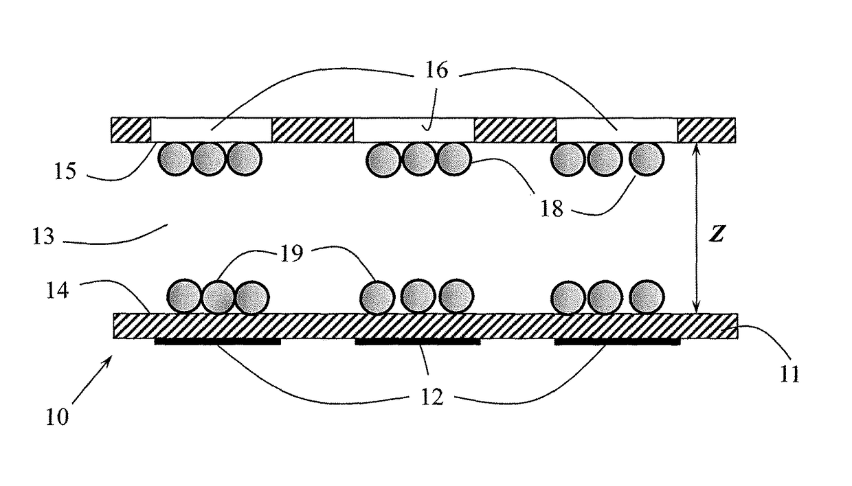
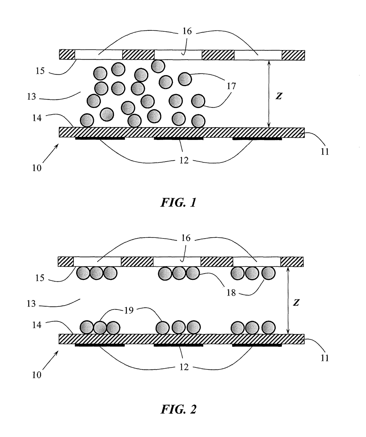
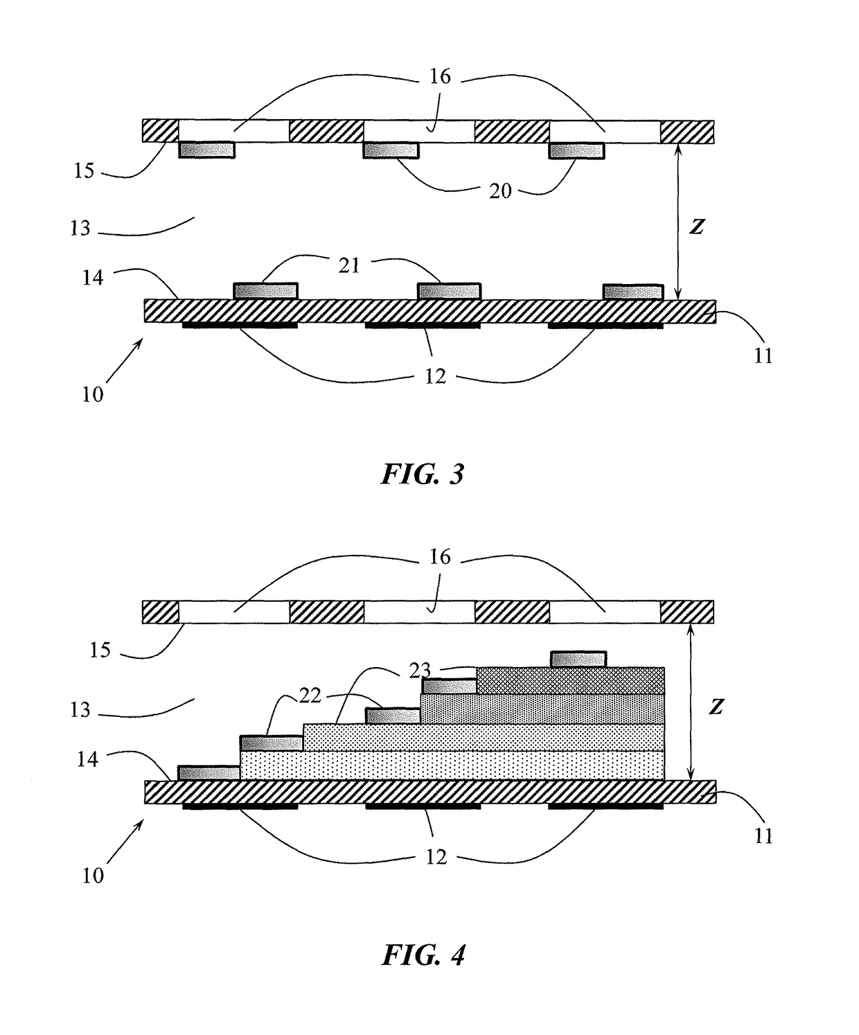
This patent is about improving methods and devices to monitor and control temperature in microfluidic environments. The invention allows for accurate temperature monitoring and control in any area of a microfluidic device where a preparation, amplification, or detection step is performed. The method involves adjusting the temperature in a first area of the chamber where temperature monitoring is desired and detecting whether the target temperature has been reached throughout the chamber using temperature sensitive agents. The invention also provides a device for monitoring and controlling temperature in a microfluidic chamber featuring a substrate, temperature control means, and a chamber where temperature sensitive agents are disposed. Overall, the invention provides more accurate and efficient tools for studying and manipulating temperatures in microfluidic environments.

Problems solved by technology

The ability to measure temperature changes of liquids in very small volumes within a microfluidic environment presents a number of technical challenges.
Usually, the measurement requires interactions with the liquid by measuring devices which either provide poor contact due to distance and surface area available for measurement or result in heat transfer between the solution and the measuring device that may interfere with accurate measurement.

Method used


Image

  • Devices and methods for monitoring and controlling temperature in a microfluidic environment
  • Devices and methods for monitoring and controlling temperature in a microfluidic environment
  • Devices and methods for monitoring and controlling temperature in a microfluidic environment

Examples


example 1

[0064]In this experiment, 950 μL TE buffer was mixed with 5 μL of a nonionic emulsifiers such as polysorbate 20 (Tween® 20) and approximately 45 μL LC-70 or LC-80 (LCR Hallcrest, Glenview, Ill.) thermochromic liquid crystals. This mixture was used to test the temperature inside a microfluidic cartridge which was filled with silicon oil as a filler liquid. This mixture was added to one reservoir on the cartridge and approx. 1 μL was dispensed using electrowetting. The droplet was then transported through PCR zones on this cartridge to test the temperature inside the cartridge. The electrowetting and heating (from bottom of the cartridge) was performed using a commercially available R110 instrument (Advanced Liquid Logic, Morrisville, N.C.). The electrowetting movement of the thermochromic liquid crystals was successful and a transition in color from red to green to blue was observed for both liquid crystal mixtures when they passed through appropriate thermal zones inside the cartrid...

example 2

[0066]In this experiment, thermochromic liquid crystals with a color transition from clear to blue color at 94.5° C. (LCR Hallcrest, Part No. SLN33R94.5C1W) were used to calibrate the actual liquid temperature on a microfluidic cartridge, and to determine the effect of mixing on temperature distribution. One-microliter droplets of liquid crystals in aqueous solution were introduced to a temperature-controlled microfluidic device, heated from below with an external heater. Results of this experiment are briefly summarized in Table 1 below. The crystals were used to determine that 101° C. at the heater was required to raise the microchannel to 94.5° C. Further, the crystals indicated that mixing induced by moving the fluid back and forth along the channel resulted in the need to raise the heater temperature to 102° C. in order to raise the fluid to 94.5° C. Presumably, an increase in heat dissipation and / or thermal uniformity of the fluid was responsible for this mixing result. Withou...


PUM

PropertyMeasurementUnit
temperatureaaaaaaaaaa

Abstract

The present invention provides improved methods that allow accurate monitoring and / or control of temperature changes in a microfluidic environment. An advantage of the present invention is that the temperature can be monitored and / or controlled at any location within a microfluidic device, especially where a preparation step, an amplification step and / or a detection step is performed. The invention further provides improved microfluidic devices for practicing the methods disclosed and claimed herein.

Description

CROSS-REFERENCE TO RELATED APPLICATION[0001]This patent application claims the benefit of U.S. Provisional Patent Application No. 61 / 800,572, filed Mar. 15, 2013.FIELD OF THE INVENTION[0002]The present invention generally relates to the field of thermal management. More specifically, the invention is concerned with devices and methods for monitoring and controlling temperature in a microfluidic environment, particularly in digital microfluidics applications such as electrowetting.BACKGROUND OF THE INVENTION[0003]The presence and concentration of target biological analytes, such as, nucleic acids or proteins, in a sample fluid containing one or more other molecules can be determined by using the complex binding of these target biological compounds with probes. For example, a set of specific probes, each of which is chosen in order to interact specifically (i.e. hybridize) with one particular target analyte, can be immobilized at specific locations of a biosensor solid substrate. The ...

Claims


Application Information

Patent Timeline
Patent Type & Authority Patents(United States)
IPC IPC(8): G01K13/00G01K11/16G05D23/27B01L3/00
CPCG01K13/00G01K11/165G05D23/27G01K2213/00B01L3/5027
Inventor SHADPOUR, HAMEDFORD, SEANGARCES, JORGE ALBERTOGRAY, DARREN S.
Owner ROCHE MOLECULAR SYST INC
Learn More