
Determining perforation orientation

a technology of perforation and orientation, applied in the direction of instruments, survey, borehole/well accessories, etc., can solve the problems of in situ optical fibre during perforation step, no useable optical signal can be received from optical fibre at locations deeper into the well, and no useable optical signal may be received from the section of optical fibre deployed in the production zon

Active Publication Date: 2018-04-17
OPTASENSE HLDG LTD
View PDF13 Cites 17 Cited by
  • Summary
  • Abstract
  • Description
  • Claims
  • Application Information

AI Technical Summary

Benefits of technology

The patent text describes a device that generates directional acoustic waves. This can be done by using a loudspeaker in a special housing or by adding a conductive material to a fibre optic cable. The technology has applications in improving sound quality and reducing noise interference.

Problems solved by technology

One problem that arises with this approach is that the optical fibre is in situ during the perforation step.
Were a perforation charge to be fired in the direction of the optical fibre, the perforation step could sever, or at least severely damage, the fibre at that location with the result that no useable optical signal can be received from the optical fibre at locations deeper into the well.
As the well may be perforated at several sections along it length, damage to the optical fibre at a section towards the top of the well could mean that no useable signals may be received from the section of fibre deployed in the production zone.
It will of course be understood that as the optical fibre is clamped in pace to the casing and cemented in place replacing a damaged optical cable is not a viable option.
However at a perforation depth which may be a kilometer or more and could be several kilometers the relative location of the fibre may not be known, and it can also be problematic to accurately orient the perforation charges.
It has been found however that such magnetic anomaly detection techniques are not always satisfactory and the magnetic signature may be masked in the downhole environment with the result that the perforator can be incorrectly aligned when fired and the optical fibre has been damaged.
Alignment of a perforator gun with respect to the optical fibre is particularly important as incorrect alignment may result in damage to the optical fibre.
However there may well be other tools that are deployed downwell, for instance via wire line, where knowing the orientation of the tool may be useful and where magnetic anomaly detection may be insufficiently accurate.

Method used


Image

  • Determining perforation orientation
  • Determining perforation orientation
  • Determining perforation orientation

Examples


Embodiment Construction

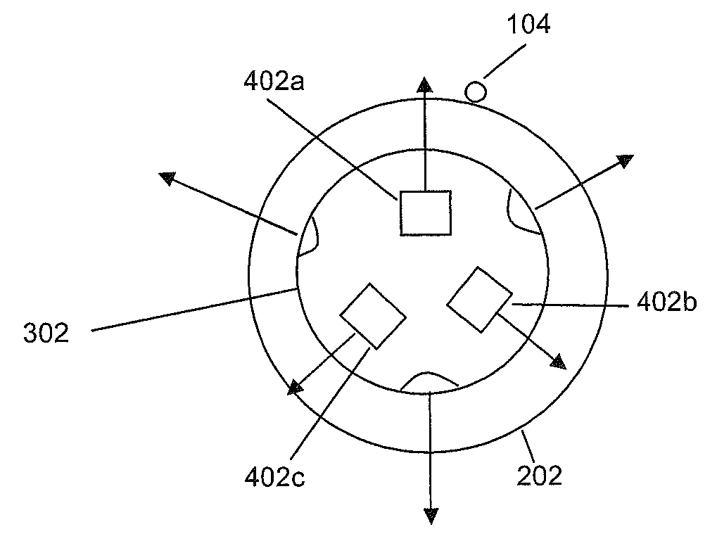
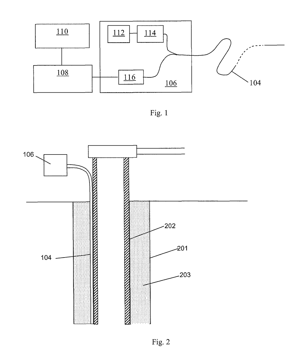
[0054]FIG. 1 shows a schematic of a distributed fibre optic sensing arrangement. A length of sensing fibre 104 is removably connected at one end to an interrogator 106. The output from interrogator 106 is passed to a signal processor 108, which may be co-located with the interrogator or may be remote therefrom, and optionally a user interface / graphical display 110, which in practice may be realised by an appropriately specified PC. The user interface may be co-located with the signal processor or may be remote therefrom.

[0055]The sensing fibre 104 can be many kilometers in length and can be at least as long as the depth of a wellbore which may be at least 1.5 km long. The sensing fibre may be a standard, unmodified single mode optic fibre such as is routinely used in telecommunications applications without the need for deliberately introduced reflection sites such a fibre Bragg grating or the like. The ability to use an unmodified length of standard optical fibre to provide sensing ...


PUM


Abstract

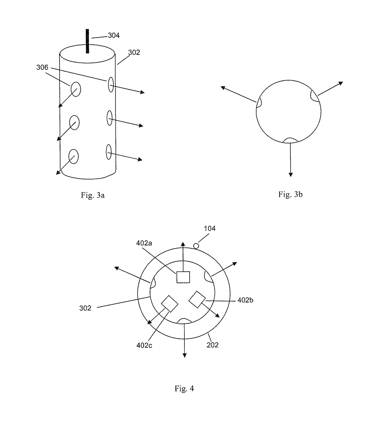
A method and apparatus for determining the relative orientation of objects downwell, and especially to determining perforator orientation, involves varying the orientation of an object, such as a perforator gun (302) in the wellbore (202) and activating at least one directional acoustic source (402a-c). Each directional acoustic source is fixed in a predetermined location to the object and transmits an acoustic signal preferentially in a known direction. The directional acoustic sources are activated so as to generate sound in a plurality of different orientations of said object. An optical fiber (104) is interrogated to provide distributed acoustic sensing in the vicinity of the object; and the acoustic signals detected by the optical fiber are analyzed to determine the orientation of the at least one directional acoustic source relative to the optical fiber, for instance by looking at the relative intensity in the different orientations.

Description

FIELD OF THE INVENTION[0001]The present invention relates to the determining the orientation of an object such as a perforator in a downwell environment and hence the direction of perforation and in particular to methods and apparatus for determining perforator orientation downwell using fibre optic distributed acoustic sensors.BACKGROUND OF THE INVENTION[0002]In typical well formation for many oil and gas wells, a well bore is drilled and then a metal casing is forced down the borehole with sections of casing being joined to one another. Once the casing is in place the outside of the casing is filled with cement, at least to a certain well depth, to effectively the seal the casing from the surrounding rock and ensure that, in use, the only flow path is through the casing. Once the cement has cured the well is typically perforated by lowering a ‘gun’ which comprises one or more shaped charges to a desired depth of the well bore.[0003]When the perforation charges are fired the shaped...

Claims


Application Information

Patent Timeline
Patent Type & Authority Patents(United States)
IPC IPC(8): E21B43/119E21B47/024E21B47/022G01V11/00E21B47/12
CPCE21B43/119E21B47/024E21B47/123E21B47/02208G01V11/005E21B47/0224E21B47/135
Inventor GODFREY, ALASTAIR
Owner OPTASENSE HLDG LTD
Learn More