
Coupled segmentation in 3D conventional ultrasound and contrast-enhanced ultrasound images

a technology of conventional ultrasound and ultrasound image, applied in the field of three-dimensional ultrasound imaging, can solve the problems of manual segmentation of organs in a 3d image, inability to realize clinical practice, and inability to provide satisfying methods,

Active Publication Date: 2018-04-03
KONINKLJIJKE PHILIPS NV
View PDF9 Cites 3 Cited by
  • Summary
  • Abstract
  • Description
  • Claims
  • Application Information

AI Technical Summary

Benefits of technology

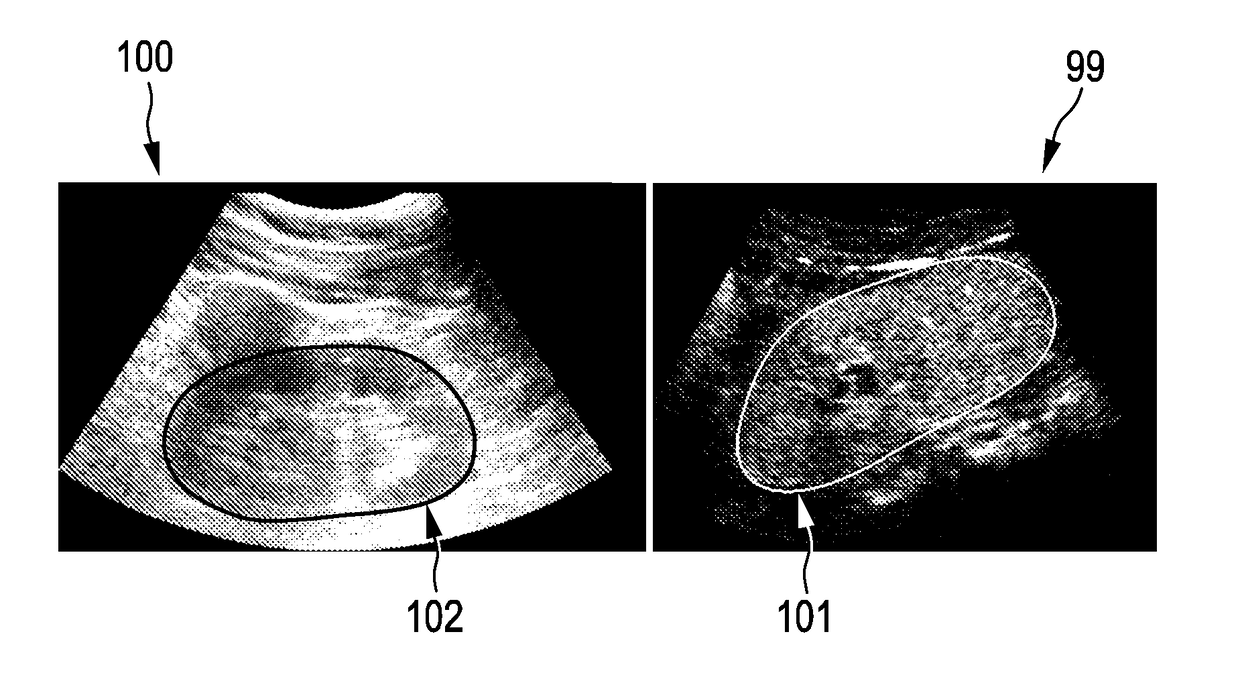
[0016]Hence, it is proposed to use simultaneously two different images, which will improve existing segmentation results. The segmentation uses complementary information in that the US image provides anatomical information, whereas the CEUS image shows the vascularization. If some parts of the target organ boundary are unclear or even missing in one of the two images, it would further be possible to extrapolate the segmentation with the information from the other image.
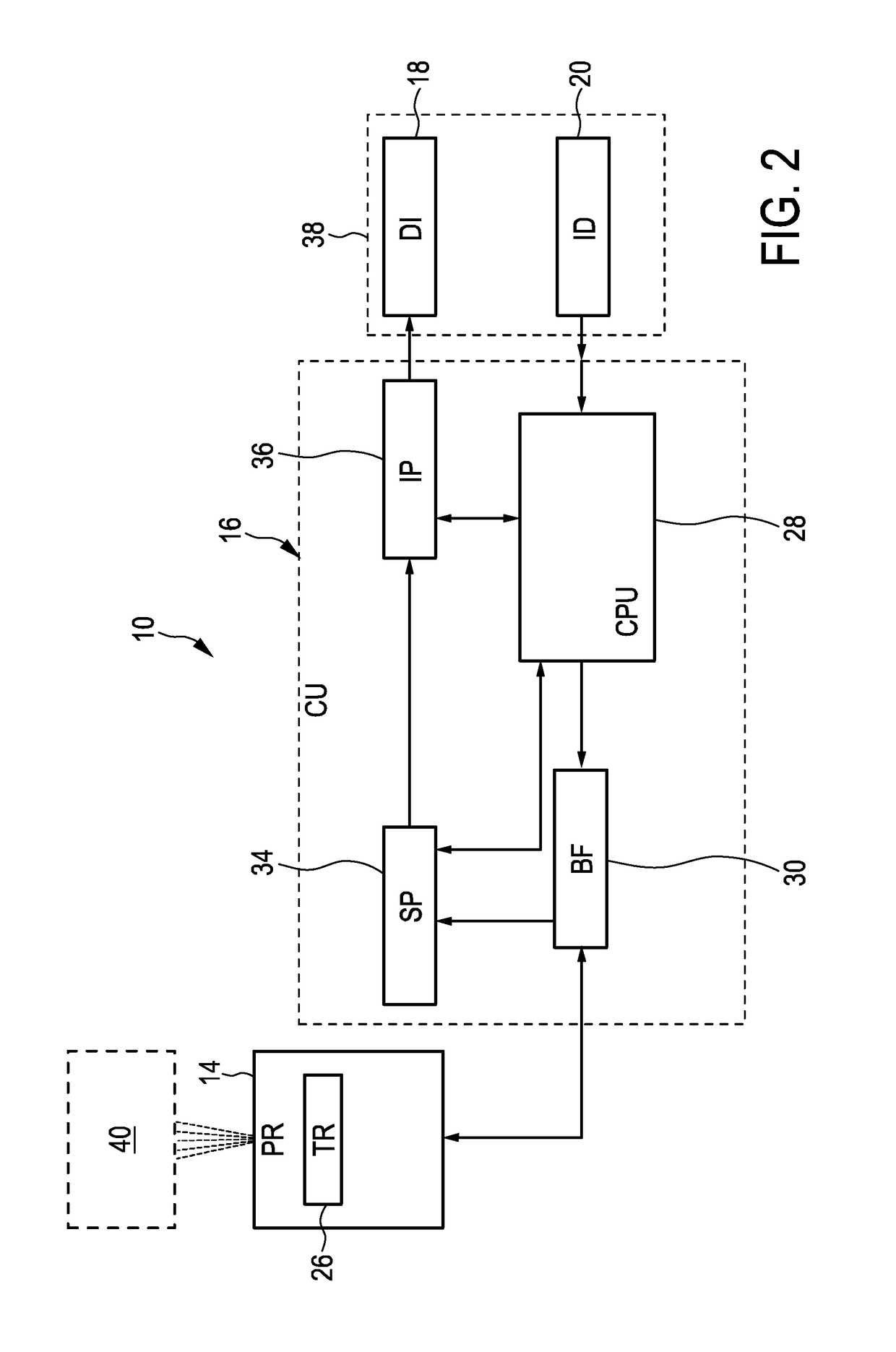
[0048]By this, a fully functioning ultrasound imaging system capable to acquire both normal three-dimensional image data and to provide it to the image processor and also capturing contrast-enhanced three-dimensional image data and providing it to the image processor is provided. This enables a user to scan a body of a patient and to view the segmented object simultaneously both as a normal ultrasound image and a contrast-enhanced ultrasound image.

Problems solved by technology

However, it is often tedious to manually segment an organ in a 3D image.
While quantification and visualization tools are relatively available for 2D images, 3D volumes analysis is often done by hand through tedious procedures impossible to realize in clinical practice.
However, such methods do not provide satisfying results.
Precise segmentations are therefore needed, but difficult to obtain, especially in ultrasound images which are corrupted by a lot of noise and various artifacts.

Method used


Image

  • Coupled segmentation in 3D conventional ultrasound and contrast-enhanced ultrasound images
  • Coupled segmentation in 3D conventional ultrasound and contrast-enhanced ultrasound images
  • Coupled segmentation in 3D conventional ultrasound and contrast-enhanced ultrasound images

Examples


Embodiment Construction

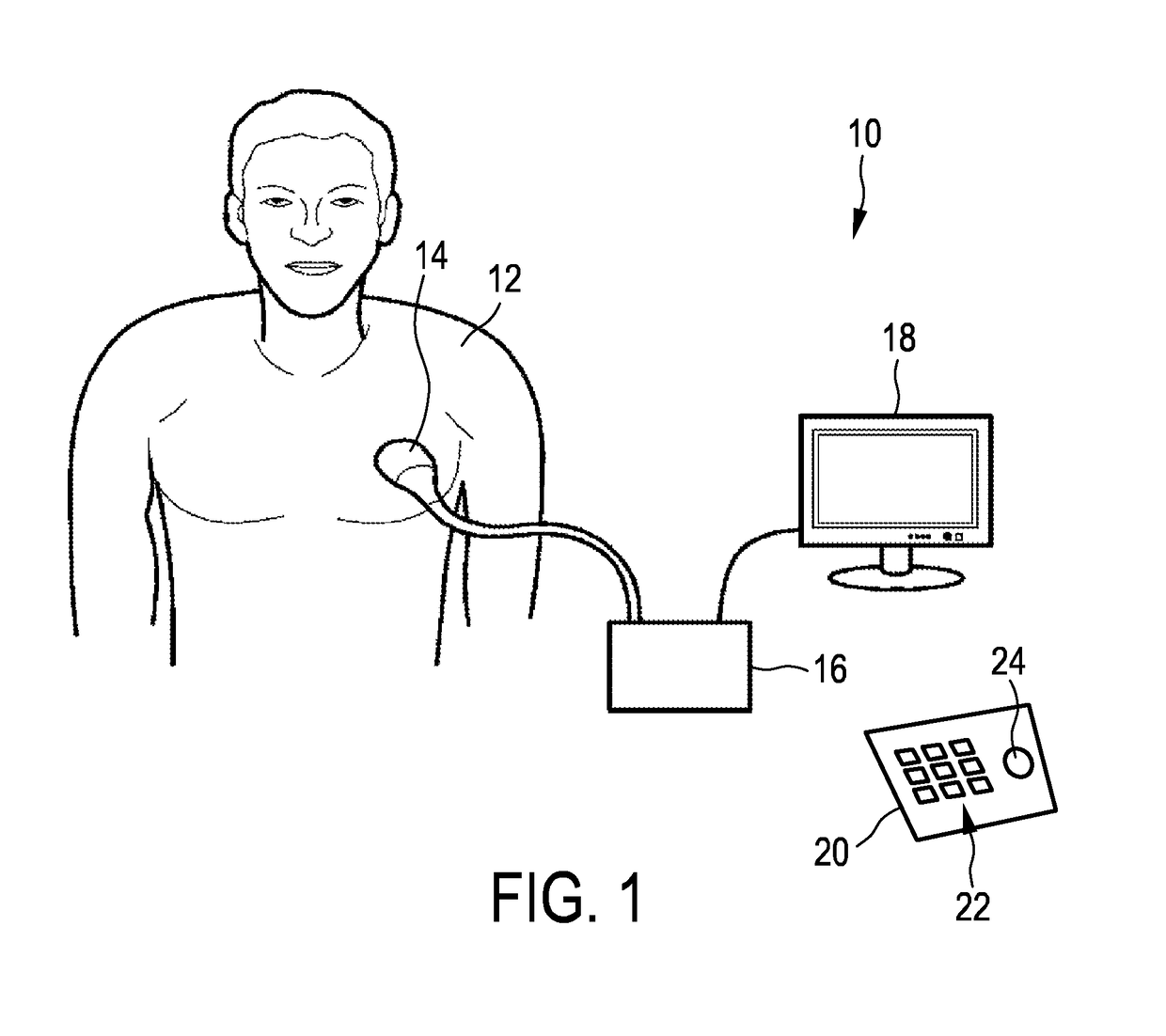
[0066]FIG. 1 shows a schematic illustration of an ultrasound system 10 according to an embodiment, in particular a medical ultrasound three-dimensional imaging system. The ultrasound imaging system 10 is applied to inspect a volume of an anatomical site, in particular an anatomical site of a patient 12. The ultrasound system 10 comprises an ultrasound probe 14 having at least one transducer array having a multitude of transducer elements for transmitting and / or receiving ultrasound waves. In one example, the transducer elements each can transmit ultrasound waves in form of at least one transmit impulse of a specific pulse duration, in particular a plurality of subsequent transmit pulses. The transducer elements can for example be arranged in a one-dimensional row, for example for providing a two-dimensional image that can be moved or swiveled around an axis mechanically. Further, the transducer elements may be arranged in a two-dimensional array, in particular for providing a multi-...


PUM


Abstract

The present invention relates to an ultrasound imaging system (10) for inspecting an object (97) in a volume (40). The ultrasound imaging system comprises an image processor (36) configured to conduct a segmentation (80) of the object (97) simultaneously out of three-dimensional ultrasound mage data (62) and contrast-enhanced three-dimensional ultrasound image data (60). In particular, this may be done by minimizing an energy tem taking into account both the normal three-dimensional ultrasound image data and the contrast-enhanced three-dimensional image data. By this, the normal three-dimensional ultrasound image data and the contrast-enhanced three-dimensional image data may even be registered during segmentation. Hence, this invention allows a more precise quantification of one organ in two different modalities as well as the registration of two images for simultaneous visualization.

Description

[0001]This application is the U.S. National Phase application under 35 U.S.C. § 371 of International Application No. PCT / IB2013 / 056676, filed on Aug. 16, 2013, which claims the benefit of EP Application No. 12306033.7 filed on Aug. 30, 2012. These applications are hereby incorporated by reference herein.FIELD OF THE INVENTION[0002]The present invention relates to three-dimensional ultrasound imaging. In particular, the current invention relates to image processing and the segmentation of objects in the scanned volume.BACKGROUND OF THE INVENTION[0003]In three-dimensional ultrasound imaging, or volume imaging, the acquisition of a three-dimensional image is accomplished by conducting many two-dimensional scans that slice through the volume of interest. Hence, a multitude of two-dimensional images is acquired that lie next to another. By proper image processing, a three-dimensional image of the volume of interest can be built out of the multitude of two-dimensional images. The three-di...

Claims


Application Information

Patent Timeline
Patent Type & Authority Patents(United States)
IPC IPC(8): G06K9/00G06T3/00G06T7/00G06T7/12G06T7/174G06T7/149
CPCG06T3/0006G06T7/12G06T7/149G06T7/174G06T2200/04G06T2207/10136G06T2207/20116G06T2207/20161G06T2207/30056G06T2207/30084G06T2207/20112G06T7/11
Inventor PREVOST, RAPHAEL MANUA MICHELARDON, ROBERTO JOSEMORY, BENOIT JEAN-DOMINIQUE BERTRAND MAURICE
Owner KONINKLJIJKE PHILIPS NV
Learn More