Image forming apparatus

a technology of image forming apparatus and forming blade, which is applied in the direction of electrographic process apparatus, instruments, developers, etc., can solve the problems of insufficient photoconductor lifetime, insufficient abrasion amount of the surface layer of the photoconductor, and inability to precisely define the surface layer grinding of the photoconductor. toner by only the cleaning blade, etc., to achieve the effect of prolonging the lifetime of the photoconductor

Active Publication Date: 2018-04-03
CANON KK
View PDF7 Cites 1 Cited by
  • Summary
  • Abstract
  • Description
  • Claims
  • Application Information

AI Technical Summary

Benefits of technology

[0009]The present invention is directed to an image forming apparatus capable of suppressing accumulation of discharge products to prolong the lifespan of an photoconductor.

Problems solved by technology

This causes difficulty in cleaning the toner by only the cleaning blade.
In Japanese Patent Application Laid-Open No. 2009-300860, however, grinding of the surface layer of the photoconductor and an abrasion amount of the surface layer of the photoconductor are not precisely defined.
This degrades a surface property of the photoconductor, and thus the lifetime of the photoconductor cannot be sufficiently prolonged.

Method used


Image

  • Image forming apparatus
  • Image forming apparatus
  • Image forming apparatus

Examples


second exemplary embodiment

[0087]A configuration of an image forming apparatus of the present exemplary embodiment is similar to that of the first exemplary embodiment. In the present exemplary embodiment, a drum heater 300 is disposed inside a photoconductor 1. The drum heater 300 controls temperature of a surface layer of the photoconductor 1. Hereinafter, the drum heater 300 is described.

(Drum Heater)

[0088]Next, the drum heater 300 according to the present exemplary embodiment is described with reference to FIG. 8. A planar heat generator in which a heat generation coil is arranged on a sheet made of polycarbonate is used as the drum heater 300 serving as a heating member of an image bearing member. The planer heat generator is disposed inside the photoconductor 1 in a state that the planer generator is set in cylindrical shape. As illustrated in FIG. 8, the planer heat generator is attached to the photoconductor 1. That is, the drum heater 300 is attached along the inside of the photoconductor 1. The plan...


PUM

PropertyMeasurementUnit
humidityaaaaaaaaaa
temperatureaaaaaaaaaa
particle diameteraaaaaaaaaa

Abstract

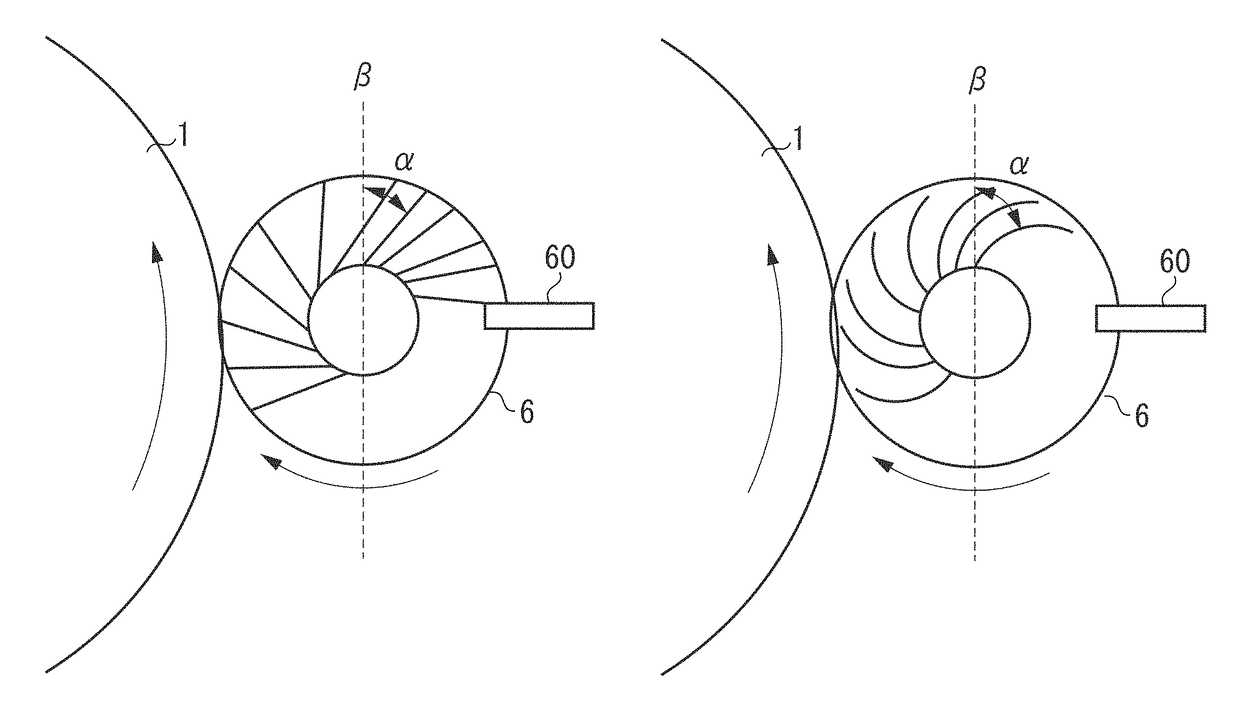
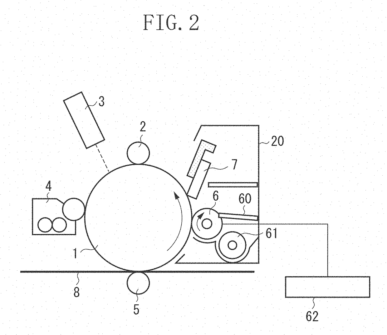
An elastic deformation rate of a photoconductor, an additive amount of inorganic fine particles, and a rotary member are set to satisfy a relation of 0.6≤(D / (A×B / C)) / (1+E / 20)≤0.82, where A is a thickness of fibers of a brush, B is a bristle density of the fibers of the brush, C is a length of the fibers of the brush, D is an elastic deformation rate obtained from a hardness test conducted using a Vickers diamond pyramid indenter at a temperature of 23° C. and a humidity of 50%, and E is the additive amount of the inorganic fine particles relative to 100 parts by mass of toner particles.

Description

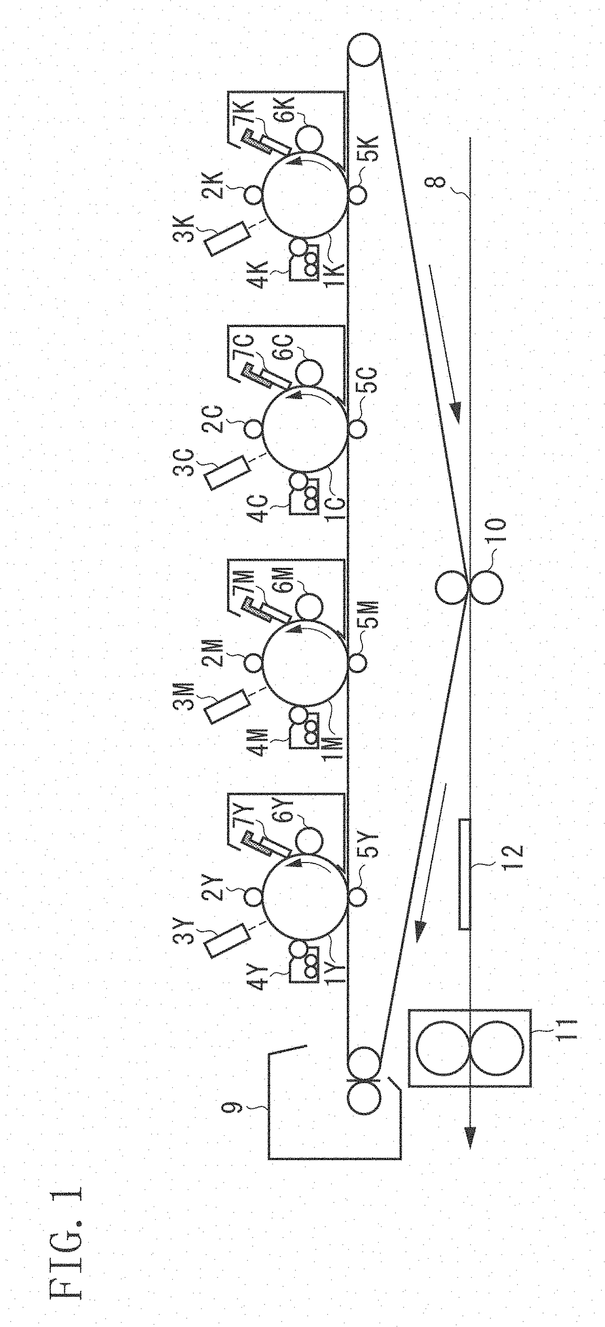
BACKGROUND OF THE INVENTION[0001]Field of the Invention[0002]The present invention relates to an electrophotographic image forming apparatus.[0003]Description of the Related Art[0004]Conventionally, in the electrophotographic image forming method, a surface of an image bearing member is charged, the charged surface of the image bearing member is irradiated with light to form an electrostatic latent image, the electrostatic latent image is developed with a coloring toner to form a visible image, the toner image is transferred to a transfer sheet, and the transferred toner image is fixed with a heat roller. After the transfer process, an external additive, an untransferred toner, and a discharge product remaining on the surface of the image bearing member need to be removed by a cleaning unit prior to a next image forming process. The cleaning unit for removing, for example, the transfer residual toner, employs various methods, such as a method using a fur brush or a magnetic brush, a...

Claims


Application Information

Patent Timeline
Patent Type & Authority Patents(United States)
IPC IPC(8): G03G21/00G03G15/00G03G5/00
CPCG03G21/0035G03G5/00G03G21/0076G03G21/0011G03G15/751G03G5/147G03G9/09708
Inventor FUKUDA, TADASHIKAMIMORI, YASUKI
Owner CANON KK
Why Eureka
Try Eureka