Portable resetting device

a resetting device and portable technology, applied in the field of medical systems, can solve the problems of pain, dislocation of joints, drug administration, etc., and achieve the effect of improving patient comfort and physical activity, reducing pain, and improving patient comfor

Active Publication Date: 2018-04-03
HORVATH PETER
View PDF9 Cites 0 Cited by
  • Summary
  • Abstract
  • Description
  • Claims
  • Application Information

AI Technical Summary

Benefits of technology

[0017]The present invention is thus achieved by a portable resetting device that overcomes the above disadvantages and provides a device that assures painless reduction of the shoulder dislocation.
[0018]The device of the present invention is directed at a goal of providing a pain-free position while relocating the humerus head into the tablet. The device of the present invention for reduction of a shoulder dislocation provides a portable resetting device having an underarm support of adjustable height upon a pedestal with the resetting device being located near to a chair having the patient therein and the injured arm on the same side as the resetting device. The resetting device is portable and thus may be readily moved to the patient. A traction structure suitable for transmitting a mechanical force in a downward direction to the injured arm is mounted to a lower support that is further mounted to the top of the pedestal. The traction structure has the lower support / section / part connected to the pedestal. A computer controllable motor is operatively connected between the lower support and the pedestal so that an angle of tilt may be placed thereon. An arm-holding plate that serves to hold the injured arm is attached to the lower support having arm holding supports and / or cuffs attached that keep the arm in a bent and fixed position; the arm-holding plate and the lower support of the traction structure are slideably connected to each other so as to permit them to move in the longitudinal direction with respect to each other by means of another computer controllable motor operatively connected therebetween. An auxiliary arm support is operatively connected by a controllable motor on the lower support. The pedestal includes the controllable motors for moving the lower support in angular displacement and for adjustment in the height of the underarm support. Appropriate electronic circuits are provided to control the motors, to display device information, and to remotely control the motors. The resetting device may further be connected through a network or the Internet to a central office where patient treatment information may be placed in a database and a treatment plan provided.
[0021]It is another aspect of the present invention to provide a means for measuring the force of extension of the joint so that the physician can control the application of force to the shoulder in an accurate manner;

Problems solved by technology

This is a painful injury.
It is a well known fact that moving the dislocated joint is painful so most methods are not even attempted without administering pain reduction drugs.
Their disadvantage is the length of the traction pull and the solutions used to exert force can cause pain because of possible displacements of the arm; therefore drugs (sedatives, local anesthesia, muscle relaxants) are generally needed.
Administering drugs, however, can always be associated with side effects, including serious complications.
The above methods may present one or more disadvantages to the patient.
For example, the position of the arm changes during pulling by manual force thus causing pain.
It also has the disadvantage that the extent and strength of the pulling force cannot be measured exactly in relation to the extension of the arm; one of the main reasons for failure, however, is that the physician gets tired and gives up.

Method used


Image

  • Portable resetting device
  • Portable resetting device
  • Portable resetting device

Examples


Embodiment Construction

[0039]The present invention is directed at a resetting device for reduction of a shoulder dislocation that minimizes pain, and further eliminates or greatly reduces the need for any pain drugs for the procedure.

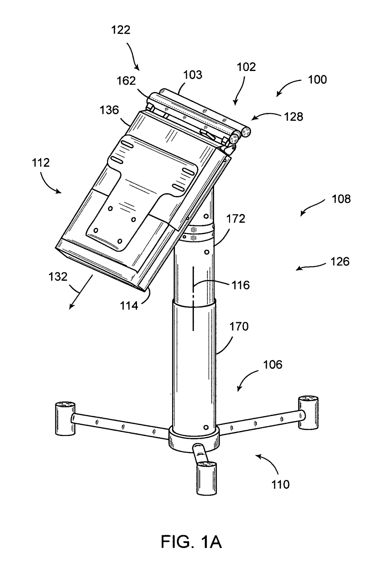
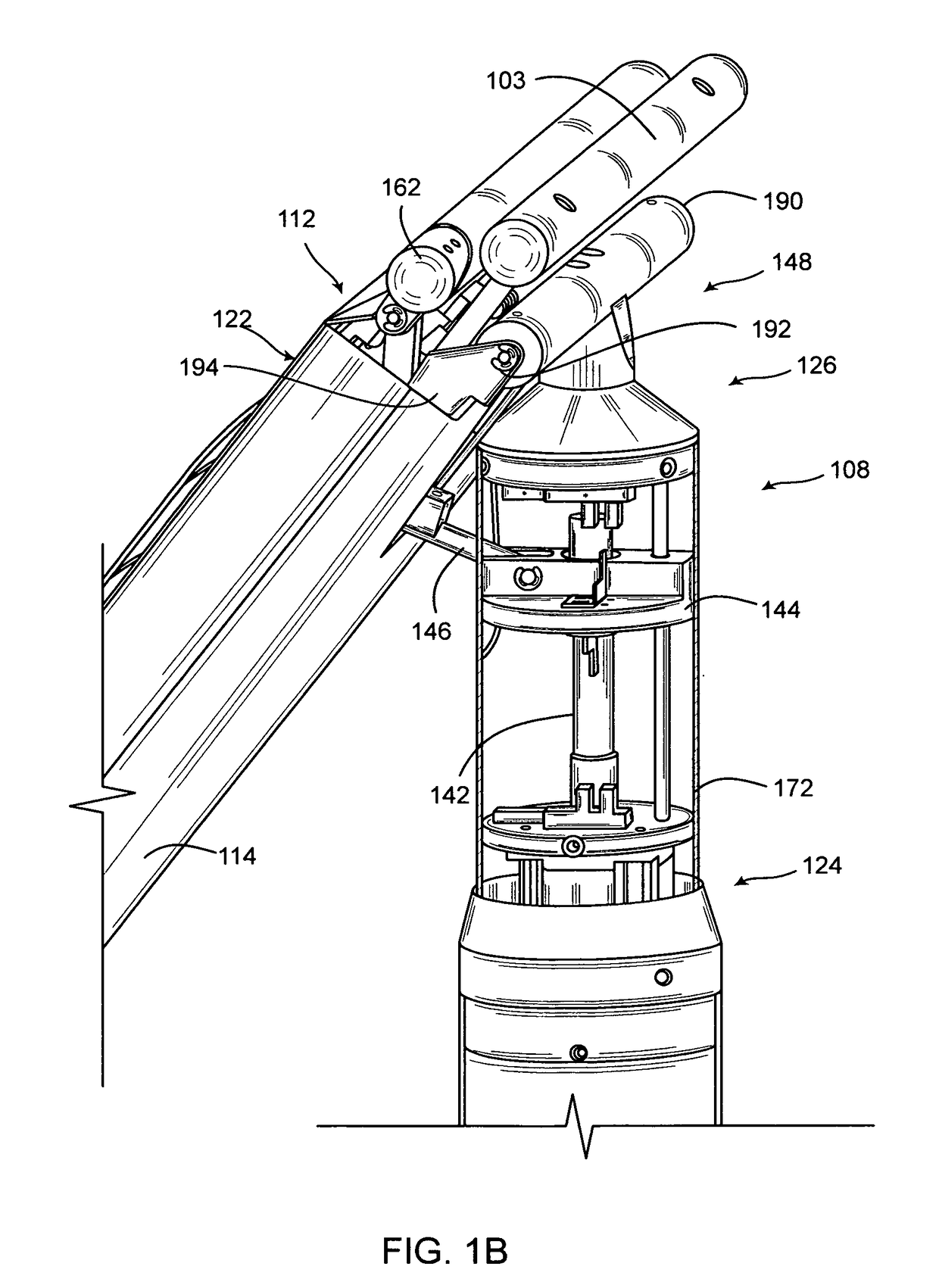
[0040]Turning to the drawings, wherein like components are designated by like reference numerals throughout the various figures, attention is initially directed to FIGS. 1A to 1F which illustrate a resetting device 100, and, in particular, FIG. 1A which is a front-side perspective view of an embodiment of the resetting device 100.

[0041]In FIG. 1A, a right side injured shoulder, for example, not shown, is supported by an underarm support 102 having an underarm support member 103. A patient, not shown, is sitting in a chair, not shown, facing the front with the right arm, not shown, over the underarm support member 103 with the armpit resting against the underarm support member 103. The height of the underarm support 102 can be adjusted by a computer controlled motor 104, FIG. ...


PUM


Abstract

The portable resetting device (100) has a portable pedestal (126) with telescoping sections (172 / 170). An underarm support (102) of adjustable height is mounted to a lower support (114) that is mounted to the pedestal (126). A traction structure (112) for transmitting forces to an injured arm is mounted to the lower support (114). A computer controllable motor (124) is operatively connected between the lower support (114) and the pedestal (108) so that an angle of tilt (116) may be placed thereon. An arm-holding plate (136) is attached to the lower support (114) and moves in a longitudinal direction by means of another computer controllable motor (118) operatively connected therebetween. An auxiliary arm support (122) is operatively connected by a computer controllable motor (120) on the lower support (114) and provides an additional force to the humerus head. A computer (302) controls the resetting device (100) and may communicate to a support computer (210) for treatment advice.

Description

CROSS REFERENCE TO RELATED APPLICATIONS[0001]The present patent application is a continuation-in-part to International Patent Application PCT / US2008 / 003516 filed on 18 Mar. 2008, and is a continuation-in-part to and claims priority to Hungarian Patent Application Serial Number P 07 00228 filed on 20 Mar. 2007, and is a continuation-in-part to U.S. patent application Ser. No. 12 / 309,366 filed Jan. 15, 2009 by the same inventor.REFERENCE TO FEDERALLY SPONSORED RESEARCH OR DEVELOPMENT[0002]NAREFERENCE TO JOINT RESEARCH AGREEMENTS[0003]NAREFERENCE TO SEQUENCE LISTING[0004]NABACKGROUND OF THE INVENTION[0005]Field of the Invention[0006]The present invention relates generally to medical systems for use in the treatment of injuries, and, in particular, relates to a device for treating joint injuries, and, in great particularity, relates to a device for resetting a joint dislocation, and in greater particularity, relates to an electro-mechanical means for controlling the treatment to minimiz...

Claims


Application Information

Patent Timeline
Patent Type & Authority Patents(United States)
IPC IPC(8): A61F5/00A61F5/04A61H1/02
CPCA61H1/0281A61F5/04A61H2203/0431
Inventor HORVATH, PETER
Owner HORVATH PETER
Why Eureka
Try Eureka