Star tracker

a star tracker and tracker technology, applied in the field of star trackers, can solve the problems of limiting the number of navigational stars that may be used, aiming a star tracker, and consuming a significant fraction of electrical power

Active Publication Date: 2018-03-27
CHARLES STARK DRAPER LABORATORY
View PDF9 Cites 7 Cited by
  • Summary
  • Abstract
  • Description
  • Claims
  • Application Information

AI Technical Summary

Benefits of technology

[0029]The computer readable program code may also cause the processor to compensate for a degree to which the unpolarized electromagnetic radiation is polarized.

Problems solved by technology

The digital camera also typically constitutes a large fraction of the electronics of the star tracker, and it consumes a significant fraction of the electrical power consumed by the star tracker.
However, the fixed view angle of a strap-down star tracker limits the number of navigational stars that may be used.
However, aiming a star tracker, relative to its vehicle, with the required precision, poses substantial problems.
The Chu device is, therefore, not useful as a star tracker, particularly in space.

Method used


Image

  • Star tracker
  • Star tracker
  • Star tracker

Examples


Embodiment Construction

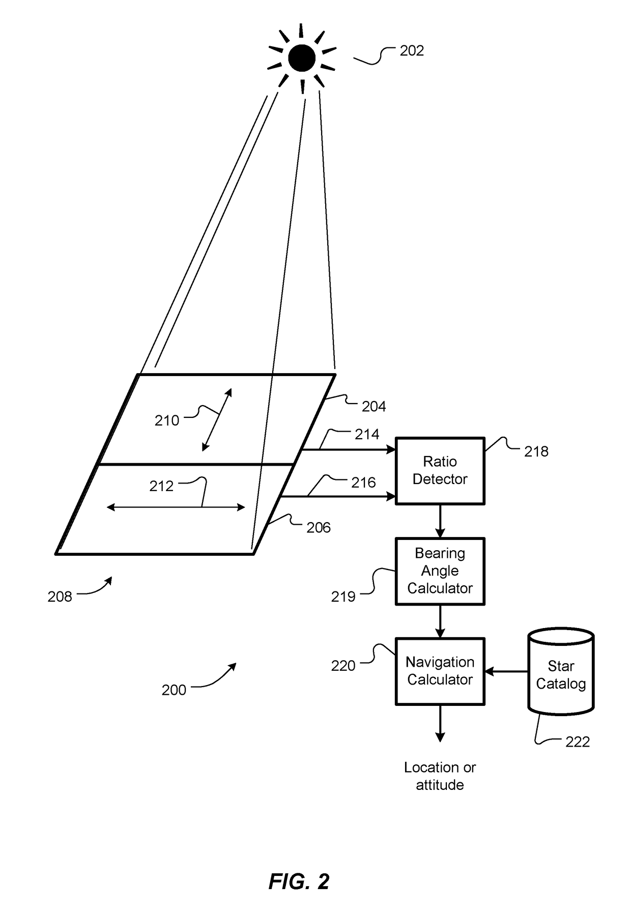
[0009]An embodiment of the present invention provides a method for determining a direction to a source of unpolarized electromagnetic radiation. The method includes exposing a first sensor to the unpolarized electromagnetic radiation. The first sensor is primarily sensitive to electromagnetic radiation polarized along a first axis. The first sensor is configured to generate a first signal proportional to a magnitude of the unpolarized electromagnetic radiation detected by the first sensor. The method also includes exposing a second sensor to the unpolarized electromagnetic radiation. The second sensor is primarily sensitive to electromagnetic radiation polarized along a second axis. The second axis is different than the first axis. The second sensor is configured to generate a second signal proportional to a magnitude of the unpolarized electromagnetic radiation detected by the second sensor. The method also includes determining a ratio of the first signal to the second signal. An a...


PUM


Abstract

A star tracker determines a location or orientation of an object, such as a space vehicle, by observing unpolarized light from one or more stars or other relatively bright navigational marks, without imaging optics, pixelated imaging sensors or associated pixel readout electronics. An angle of incidence of the light is determined by comparing signals from two or more differently polarized optical sensors. The star tracker may be fabricated on a thin substrate. Some embodiments have vertical profiles of essentially just their optical sensors. Some embodiments include micro-baffles to limit field of view of the optical sensors.

Description

CROSS REFERENCE TO RELATED APPLICATIONS[0001]This application claims the benefit of U.S. Provisional Patent Application No. 62 / 033,961, filed Aug. 6, 2014, titled “Star Tracker,” the entire contents of which are hereby incorporated by reference herein, for all purposes.TECHNICAL FIELD[0002]The present invention relates to star trackers and, more particularly, to star trackers having polarized sensors, rather than imaging optics.BACKGROUND ART[0003]Most artificial satellites, spacecraft and other craft such as aircraft, ship and ground vehicles (collectively referred to herein as vehicles) require information about their locations and / or attitudes to accomplish their missions. This information may be obtained from one or more sources, such as the global positioning system (GPS), ground-based radar tracking stations and / or on-board star trackers.[0004]A star tracker is an optical device that measures angles to one or more stars, as viewed from a vehicle. A star tracker typically inclu...

Claims


Application Information

Patent Timeline
Patent Type & Authority Patents(United States)
IPC IPC(8): G01C21/02G01S3/786G01C3/08
CPCG01C3/085G01S3/7867
Inventor WALDRON, ERIK L.LAINE, JUHA-PEKKA J.BLASCHE, GREGORY P.CHAPARALA, MURALI V.DAWSON, ROBIN MARK ADRIANLANE, BENJAMIN F.SMITH, STEPHEN P.
Owner CHARLES STARK DRAPER LABORATORY
Why Eureka
Try Eureka