
Peripheral filtering star tracker telescope

a star tracker and peripheral filtering technology, applied in the field of optical imaging systems, can solve the problems of disadvantageous extending the over all physical length of the telescope, disadvantageous injecting signal noise into the telescope, and affecting the fidelity of on-axis images, so as to reduce photographic glare, improve photographic quality, and preserve the effect of on-axis image fidelity

Inactive Publication Date: 2010-05-18
THE AEROSPACE CORPORATION
View PDF3 Cites 8 Cited by
  • Summary
  • Abstract
  • Description
  • Claims
  • Application Information

AI Technical Summary

Benefits of technology

[0013]Yet another object of the invention is to provide optical systems using peripheral image attenuating lenses and filters that can be easily manufactured.
[0023]The periphery attenuation front-end filters and lenses can be used to enhance image tracking, human visual perception, and photographic quality. These and other advantages will become more apparent from the following detailed description of the preferred embodiment.

Problems solved by technology

Once the desired tracking star has been located and the telescope is moved to maintain tracking of that tracked star, images of the nearby stars may still disadvantageously remain within the field of view.
However, off-axis nearby star images as well as sunlight can disadvantageously inject signal noise into the telescope.
In both cases, the prior shades disadvantageously extended the over all physical length of the telescopes that are intended to fits within a predetermined and dimensionally limited existing spacecraft tracking system.
The various baffle angles have a limited angular design, and hence, disadvantageously have a limited amount of noise rejection.
However, such a shade also decreases the amount of light, and hence, decreases the image quality of the desired image to be photographed.
However, sunglasses dim on-axis vision that reduces visual acuity along an intended line-of-sight increasing the problems of poor night perception.
Star tracking telescopes, and common handheld optical apparatus, such as handheld cameras, binoculars, eyeglasses, and telescopes suffer from the problem of injecting bright off-axis noise into the image quality of on-axis images or suffer from the problem of blocking needed peripheral vision and image reception.

Method used


Image

  • Peripheral filtering star tracker telescope
  • Peripheral filtering star tracker telescope
  • Peripheral filtering star tracker telescope

Examples


Embodiment Construction

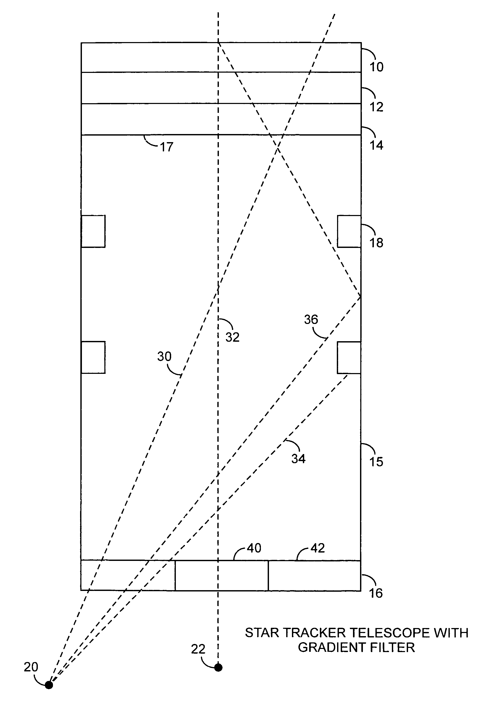
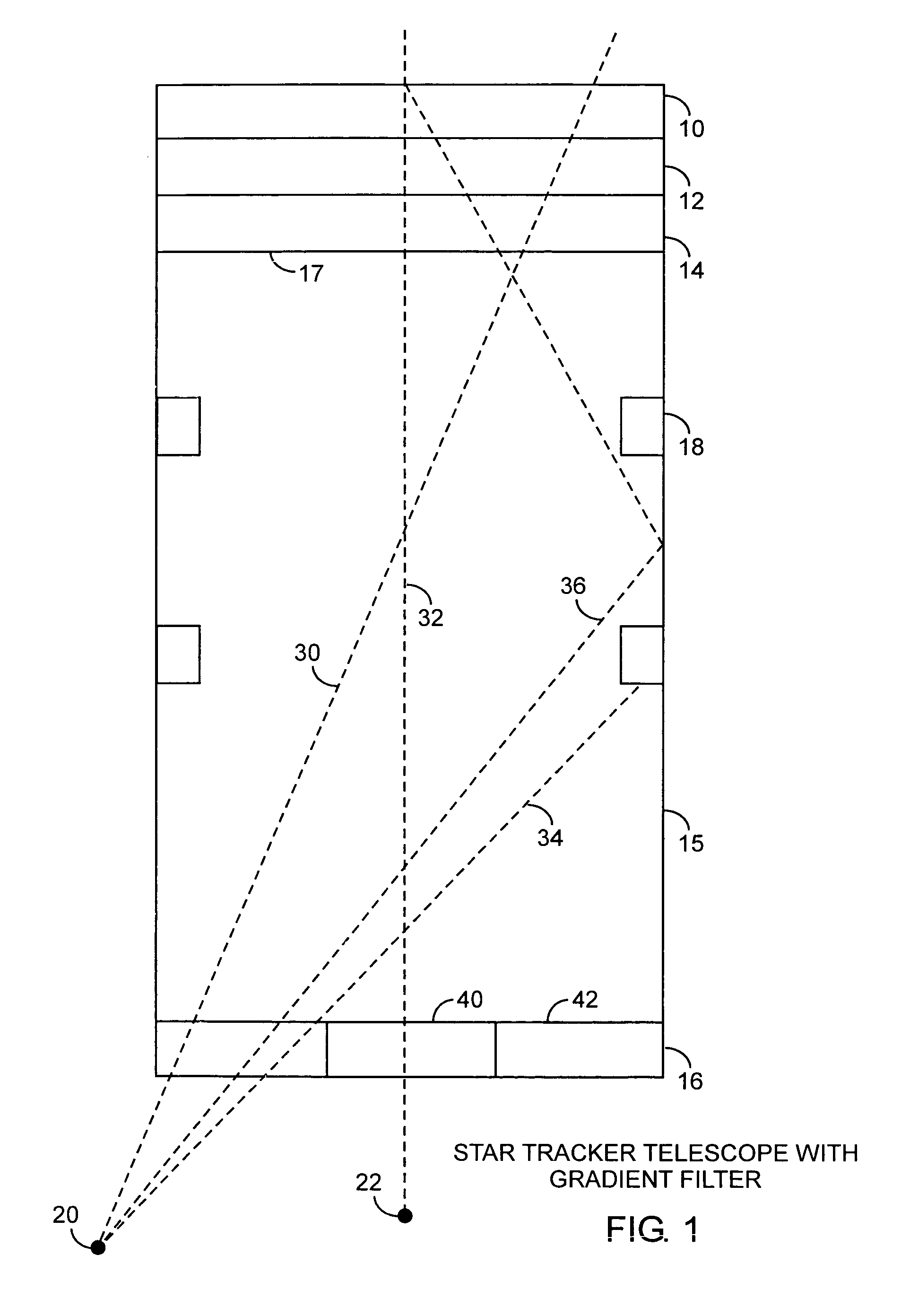
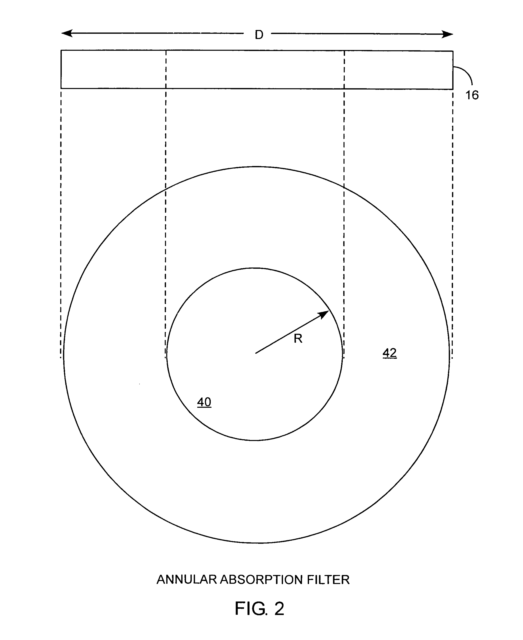
[0032]An embodiment of the invention is described with reference to the figures using reference designations as shown in the figures. Referring to FIG. 1, a star tracker telescope includes an optical sensor 10, a bandpass filter 12, an optical lens 14, a tubular shade 15, and an annular filter 16 for focusing received images upon a focal plane 17. The tubular shade 15 may include baffles 18. A bright off-axis star image 20 and a dim on-axis star image 22 provide optical images. The images pass through the annular filter 16, the focal plane 17, and optical lens 14 for activating the optical sensor 10 that provides electronic images of the bright off-axis star image 20 and the dim on-axis star image 22 for star tracking. The bright off-axis image 20 could be an image of the sun or a distal bright star. The dim on-axis star image 22 could be a dim remote star that is to be tracked.

[0033]The bright star off-axis image 20 passes through the tubular shade 15 along an attenuated bright sta...


PUM


Abstract

A filter or lens for a star-tracking telescope includes a clear center portion and an attenuating peripheral portion. The peripheral portion attenuates off-axis images through any radial line extending from a center of the filter or lens to a circumference edge of the filter or lens. The attenuation is for passing on-axis images with high signal to noise ratios, for attenuating off-axis images, and for attenuating but not completely blocking the off-axis images. The telescope with such a filter or lens is well suited for improved star tracking systems, and well suited for reducing off-axis glare in handheld optical apparatus such as binoculars, telescopes, cameras, and eyeglasses.

Description

STATEMENT OF GOVERNMENT INTEREST[0001]The invention was made with Government support under contract No. FA8802-00-C-0001 by the Department of the Air Force. The Government has certain rights in the invention.REFERENCE TO RELATED APPLICATION[0002]The present application is related to applicant's copending application entitled Peripheral Filtering Lens Ser. No. 11 / 541,190, filed Sep. 29, 2006.[0003]The present application is related to applicant's copending application entitled Peripheral Filtering Eyeglass and Camera Optical Systems Ser. No. 11 / 524,835, filed Sep. 20, 2006, by the same inventors.FIELD OF THE INVENTION[0004]The invention relates to the field of optical imaging systems. More particularly, the invention relates to star tracking telescopes having image peripheral filtering characterized as peripherally attenuating radially identical filtering.BACKGROUND OF THE INVENTION[0005]Star tracking telescopes have long been used in spacecraft for determining the location of a spac...

Claims


Application Information

Patent Timeline
Patent Type & Authority Patents(United States)
IPC IPC(8): G02B23/12
CPCG01S3/781G01S3/7867G02B5/003G02B23/00G02C7/105G02C7/16G03B11/02
Inventor LAU, KENNETH H.
Owner THE AEROSPACE CORPORATION
Learn More