
Stator of linear compressor and fixing method thereof, linear motor, and linear compressor

a linear compressor and stator technology, applied in the direction of positive displacement liquid engine, piston pump, magnetic circuit shape/form/construction, etc., can solve the problems of reducing reducing the compression efficiency, and unable to fix as tight, so as to improve the structure of the stator in the linear compressor and reduce the magnetic loss. , the effect of enhancing the efficiency of the motor

Active Publication Date: 2018-03-20
HAIER GRP CORP +2
View PDF15 Cites 0 Cited by
  • Summary
  • Abstract
  • Description
  • Claims
  • Application Information

AI Technical Summary

Benefits of technology

[0014]One of the objectives of the present invention is to provide a high-efficiency, small-volume, and high-reliability stator for a linear compressor, and a linear motor and a linear compressor including such a stator, and to provide a fixing structure and method for a stator lamination that can improve overall fastness of a stator.
[0044]Among other things, in the present invention, the structure of the stator in the linear compressor is improved, and the gap defined within the outer circumference of the stator is used. A smaller second stator piece is inserted in a relatively large gap defined between the first stator pieces so as to reduce magnetic loss caused by the gap in the stator and to enhance efficiency of the motor, and to further enhance the performance of a linear compressor. In addition, in the present invention, a filling piece is further disposed in a gap defined between adjacent first stator pieces and second stator pieces, so that the stator of the present invention has a more compact and tighter structure. The occurrence of magnetic saturation of a motor of a linear compressor is effectively avoided, and difficulties of increasing the magnetic induction intensity of the gap between the inner and outer stators and increasing the compression force because of magnetic saturation are reduced. The motor of the linear compressor has a higher driving force and more desirable stability. Performance and reliability of the linear compressor can be improved, and the volume of the linear compressor can be further reduced. Moreover, in the present invention, a through hole is disposed on a fixing component, and a protrusion for inserting in the through hole is formed on a stator lamination. The protrusion and the through hole can fit each other to fix the stator lamination to improve overall fastness of the stator.

Problems solved by technology

Especially, a stator with a coil inside usually has a relatively large volume, and thus cannot be fixed as tight as a stator without a coil.
Magnetic saturation occurring to stacked silicon steel sheets, it becomes difficult to increase the capacity of a motor.
A potential problem for the linear compressor may be that an electromagnetic force fails to drive a piston to the top dead center, therefore the compression efficiency is lowered and the efficiency of the motor is lowered.
In addition, when the motor is electrified and working, after an alternating current flows through the excitation coil on the inner stator, an induced magnetic field is produced between the inner stator and the outer stator, the interval defined between the combination forms a magnetically conductive resistance to cause a magnetic loss, therefore lower the efficiency of the motor of the compressor.
Further, because there are a number of gaps within the stators, a fringe effect exists in the magnetic field around the gap, which causes the coil of the additional loss and a relatively high temperature rise, and in severe cases, the safety and service life of the motor are affected.
To avoid the occurrence of magnetic saturation, the volume of a stator in which a coil is placed may be increased to lower the magnetic flux density; however, this causes an increased volume of the motor of the linear compressor, and further causes an increased volume of the compressor.
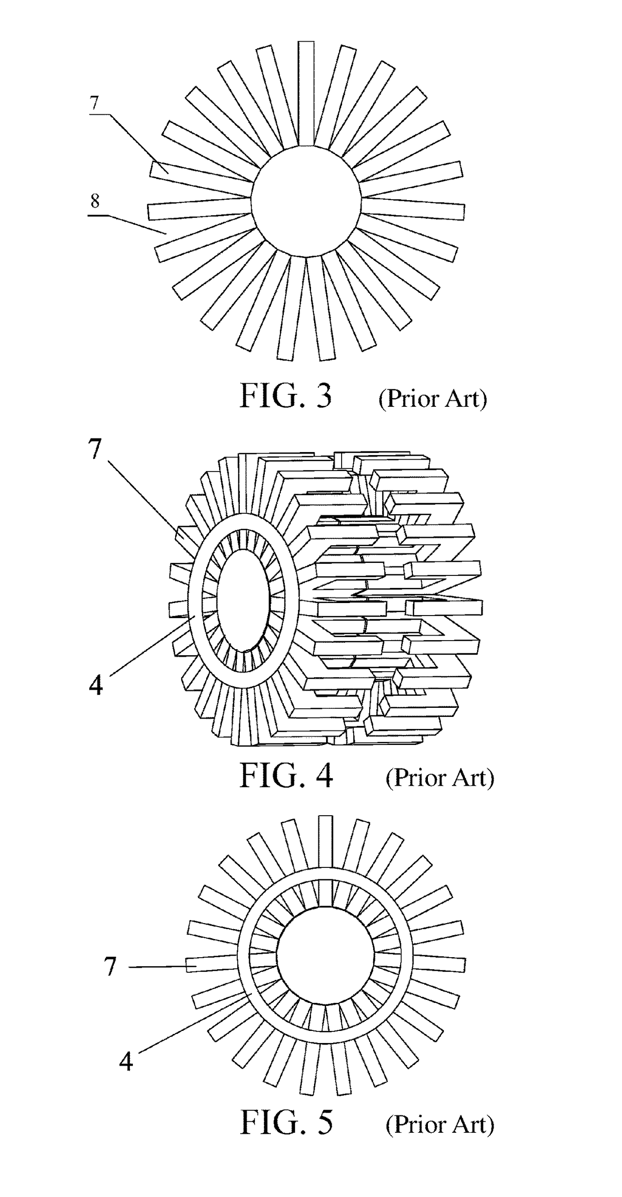
1) A corresponding protrusion or groove is stamped on the stator laminations, and adjacent stator laminations fit each other by using these protrusions and grooves. By using this method, stator laminations are not securely fixed, and become loose easily when a motor vibrates during working.
2) As shown in FIG. 4 and FIG. 5, grooves are defined at the side end of each stator lamination. When these stator laminations are formed into a cylindrical part, an annular fixing component 4 is configured in interference fit manner inside an annular space define within a groove. Because interference fit is needed in this method, during assembly, because of the effect of pressure, deformation can easily occur to a stator lamination, so that the overall size assembly precision of a linear compressor of a motor is affected.
Therefore, a heretofore unaddressed need exists in the art to address the aforementioned deficiencies and inadequacies.

Method used


Image

  • Stator of linear compressor and fixing method thereof, linear motor, and linear compressor
  • Stator of linear compressor and fixing method thereof, linear motor, and linear compressor
  • Stator of linear compressor and fixing method thereof, linear motor, and linear compressor

Examples


Embodiment Construction

[0068]The invention will now be described more fully hereinafter with reference to the accompanying drawings, in which exemplary embodiments of the invention are shown. This invention may, however, be embodied in many different forms and should not be construed as limited to the embodiments set forth herein. Rather, these embodiments are provided so that this disclosure will be thorough and complete, and will fully convey the scope of the invention to those skilled in the art. Like reference numerals refer to like elements throughout.

[0069]It will be understood that when an element is referred to as being “on” another element, it can be directly on the other element or intervening elements may be present therebetween. In contrast, when an element is referred to as being “directly on” another element, there are no intervening elements present. As used herein, the term “and / or” includes any and all combinations of one or more of the associated listed items.

[0070]It will be understood ...


PUM


Abstract

In one aspect of the present invention, a stator of a linear compressor comprises first stator pieces that are circumferentially and sequentially arranged about an axial direction and are radially disposed, second stator pieces that are provided between outer parts of the adjacent first stator pieces, and an outer side, away from a motor axis, of the second stator pieces assembled at an outer circumference of the stator. The stator can reduce the magnetic losses of the stator caused by the gap, and improve the efficiency of the motor. It can also improve the performance, stability, durability and reliability of the linear compressor. It can also reduce the bulk of the linear compressor.

Description

CROSS-REFERENCE TO RELATED APPLICATIONS[0001]This application is a continuation application of PCT Patent Application No. PCT / CN2013 / 086692, filed Nov. 7, 2013, which itself claims the priority of Chinese Patent Application Nos. 201210442338.3, filed Nov. 7, 2012, 201210482810.6, filed Nov. 23, 2012, and 201310307705.3, filed Jul. 22, 2013. Each of the above disclosures is incorporated herein in its entirety by reference.FIELD OF THE INVENTION[0002]The present invention relates generally to linear compressors, and more particularly, to a stator of a linear compressor and a fixing method thereof, and a linear motor and a linear compressor including such a stator.BACKGROUND OF THE INVENTION[0003]The background description provided herein is for the purpose of generally presenting the context of the present invention. The subject matter discussed in the background of the invention section should not be assumed to be prior art merely as a result of its mention in the background of the i...

Claims


Application Information

Patent Timeline
Patent Type & Authority Patents(United States)
IPC IPC(8): H02K1/14F04B35/04F25B1/00H02K33/06H02K33/00H02K1/34H02K15/02
CPCH02K33/00F04B35/04F04B35/045F25B1/005H02K33/06H02K1/145H02K1/34H02K15/022H02K1/14
Inventor SONG, BINLEE, HYEOMGKOOKYAN, SAINAZHAO, ZHIQIANGXU, SHENGLI, BIAO
Owner HAIER GRP CORP
Learn More