
Nuclear power generation system

a technology of nuclear power generation and nuclear power, applied in nuclear engineering, nuclear elements, greenhouse gas reduction, etc., can solve the problems of reducing the reliability and maintenance cost of the plant, reducing the efficiency of the power generation system, and reducing the complexity of the power cycle, so as to increase the thermo-siphon effect mechanism, increase the temperature differential, and maximize the heat transfer rate

Active Publication Date: 2018-03-20
SMR INVENTEC
View PDF13 Cites 2 Cited by
  • Summary
  • Abstract
  • Description
  • Claims
  • Application Information

AI Technical Summary

Benefits of technology

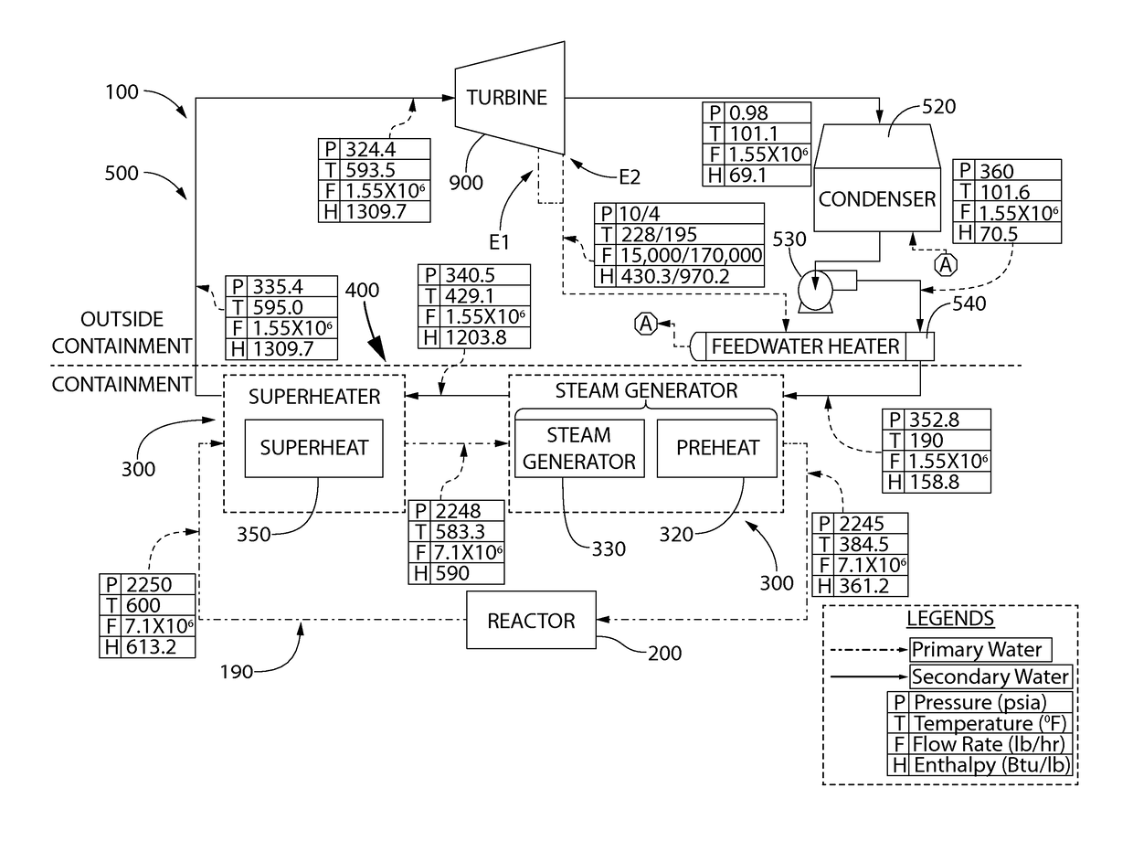
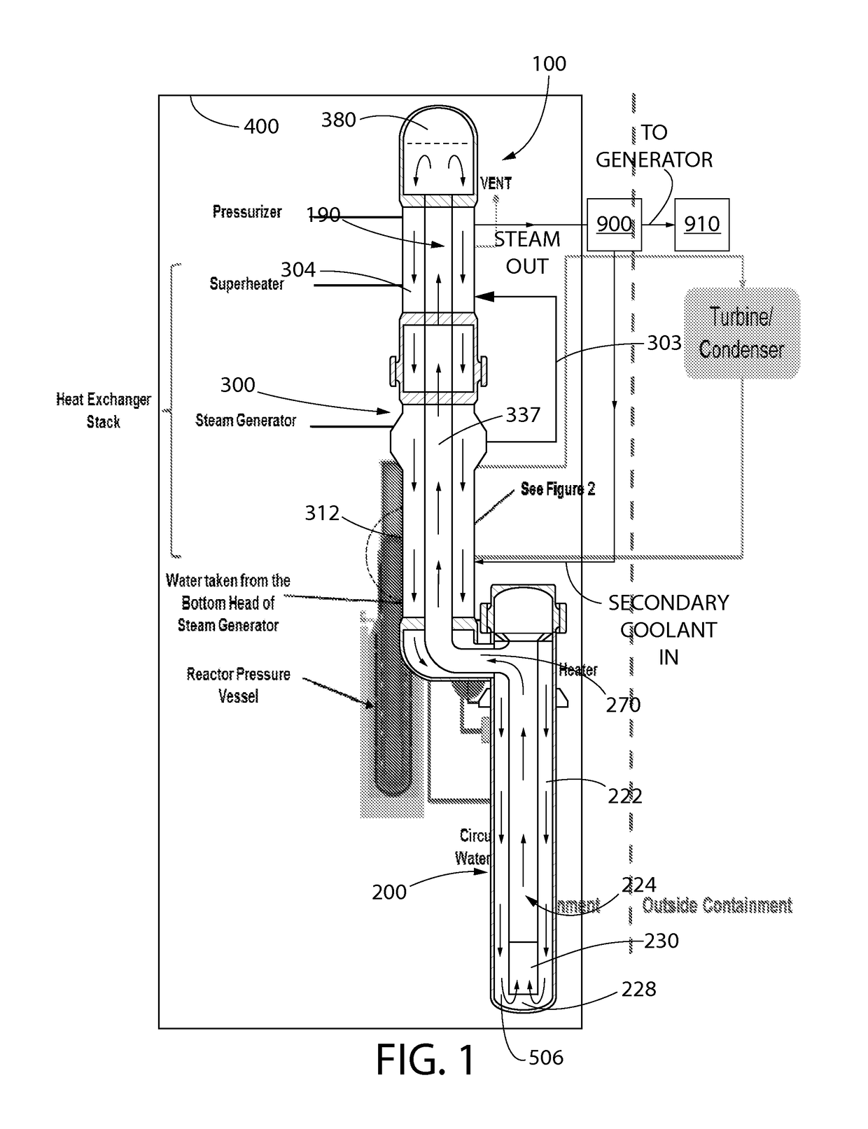
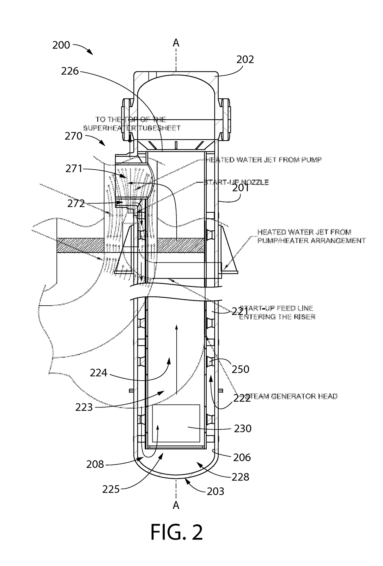
The present invention provides an improved nuclear steam supply system that uses natural thermally induced gravity flow to circulate primary coolant through the steam generating and reactor vessels, eliminating the need for a high pressure turbine. The system also includes a single feedwater heater in the secondary coolant flow or piping loop external to the reactor vessel, which minimizes heating of the liquid phase secondary coolant upstream and outside of the steam generator in the balance of plant. This results in a larger temperature differential initially between the primary coolant and secondary coolant in the steam generator, enhancing the thermo-siphon effect mechanism of the natural convection-based gravity-driven primary coolant circulation system and rate of primary coolant flow, thereby eliminating the need for primary coolant pumps.

Problems solved by technology

The array of steam turbines, feedwater heaters, MSR, and associated piping, valves and instrumentation, typical of modern nuclear plants, are also a known source of reduction in the plant's reliability and increase in maintenance costs.
Although the foregoing equipment mentioned may add perhaps one to two percent to the plant's thermodynamic efficiency, the concomitant increase in complexity, capital cost, and detriment to the plant's availability may be quite significant.
In particular, the complexity of the power cycle detracts from the use of the nuclear plant as a variable power supply source for cyclical “load following” operation.

Method used


Image

  • Nuclear power generation system
  • Nuclear power generation system
  • Nuclear power generation system

Examples


Embodiment Construction

[0019]The features and benefits of the invention are illustrated and described herein by reference to non-limiting exemplary embodiments. This description of exemplary embodiments is intended to be read in connection with the accompanying drawings, which are to be considered part of the entire written description. Accordingly, the disclosure expressly should not be limited to such exemplary embodiments illustrating some possible non-limiting combination of features that may exist alone or in other combinations of features.

[0020]In the description of embodiments disclosed herein, any reference to direction or orientation is merely intended for convenience of description, and is not intended in any way to limit the scope of the present invention. Relative terms such as “lower,”“upper,”“horizontal,”“vertical,”, “above,”“below”“up,”“down,”“top” and “bottom” as well as derivative thereof (e.g., “horizontally,”“downwardly,”“upwardly,” etc.) should be construed to refer to the orientation ...


PUM


Abstract

A nuclear power generation system and related power cycle are disclosed, in one embodiment, the system includes primary coolant circulation through a hydraulically interconnected reactor containing nuclear fuel and a steam generating vessel collectively defining a steam supply system. Liquid secondary coolant for the power cycle flows through the steam generating vessel and is converted to steam by the primary coolant to drive a low pressure turbine of a turbine-generator set. Steam exiting the turbine is condensed and heated prior to return to the steam supply system, thereby completing a secondary coolant flow loop. In one embodiment, a majority of the secondary coolant heating occurs within the steam generating vessel via heat exchange with the primary coolant rather than externally in the secondary coolant flow loop. This creates a temperature differential between the primary and secondary coolant sufficient to create natural thermally induced convective circulation of the primary coolant.

Description

CROSS-REFERENCE TO RELATED PATENT APPLICATIONS[0001]The present application is a U.S. national stage application under 35 U.S.C. § 371 of PCT / US2013 / 066777 filed Oct. 25, 2013, which claims the benefit of U.S. Provisional Patent Application No. 61 / 718,309 filed Oct. 25, 2012, the entireties of which are herein by reference.FIELD OF THE INVENTION[0002]The present invention relates to nuclear power generation systems, and more particularly to a steam supply system and related power cycle including natural thermally induced gravity flow of primary coolant through a reactor and steam generator.BACKGROUND OF THE INVENTION[0003]Commercial nuclear power generation plants in use as well as those thus far submitted for licensing approval in the United States and abroad are characterized by the following common features with respect of their power generation cycle (e.g. Rankine cycle). First, the motive steam produced which is used to drive the steam turbine is produced at a moderately high p...

Claims


Application Information

Patent Timeline
Patent Type & Authority Patents(United States)
IPC IPC(8): G21D5/14G21C15/26G21D1/00G21C13/10G21D5/16
CPCG21D1/006G21C13/10G21D5/14G21D5/16G21C15/26Y02E30/40Y02E30/00Y02E30/30
Inventor SINGH, KRISHNA P.RAJKUMAR, JOSEPH
Owner SMR INVENTEC
Learn More