
Thermal clutch for thermal control unit and methods related thereto

a technology of thermal control unit and thermal clutch, which is applied in process control, machine control, semiconductor/solid-state device testing/measurement, etc., can solve the problems of limiting the maximum thermal transfer capability of the tec, and prolonging the testing tim

Active Publication Date: 2018-03-20
LTI HLDG INC
View PDF38 Cites 4 Cited by
  • Summary
  • Abstract
  • Description
  • Claims
  • Application Information

AI Technical Summary

Benefits of technology

[0036]Additionally directional terms such as “above,”“below,”“upper,”“lower,” etc. are used for convenience in referring to the accompanying drawing figures. In general, “above,”“upper,”“upward” and similar terms refer to a direction toward a proximal end of an instrument, device, apparatus or system and “below,”“lower,”“downward,” and similar terms refer to a direction toward a distal end of an instrument, device, apparatus or system, but is meant for illustrative purposes only and the terms are not meant to limit the disclosure.

Problems solved by technology

However, the use of a TEC necessarily limits the maximum thermal transfer capability as well as being prone to failure.
Moreover, as the DC flow in the TEC needs to be switched to switch the TEC between cooling and heating, a time delay results between the heating and cooling phases which time delay necessarily means lengthening of testing times.

Method used


Image

  • Thermal clutch for thermal control unit and methods related thereto
  • Thermal clutch for thermal control unit and methods related thereto
  • Thermal clutch for thermal control unit and methods related thereto

Examples


Embodiment Construction

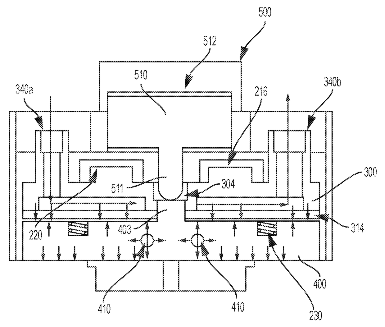
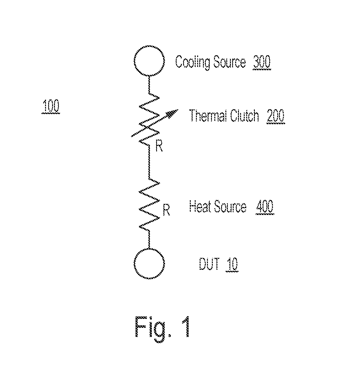
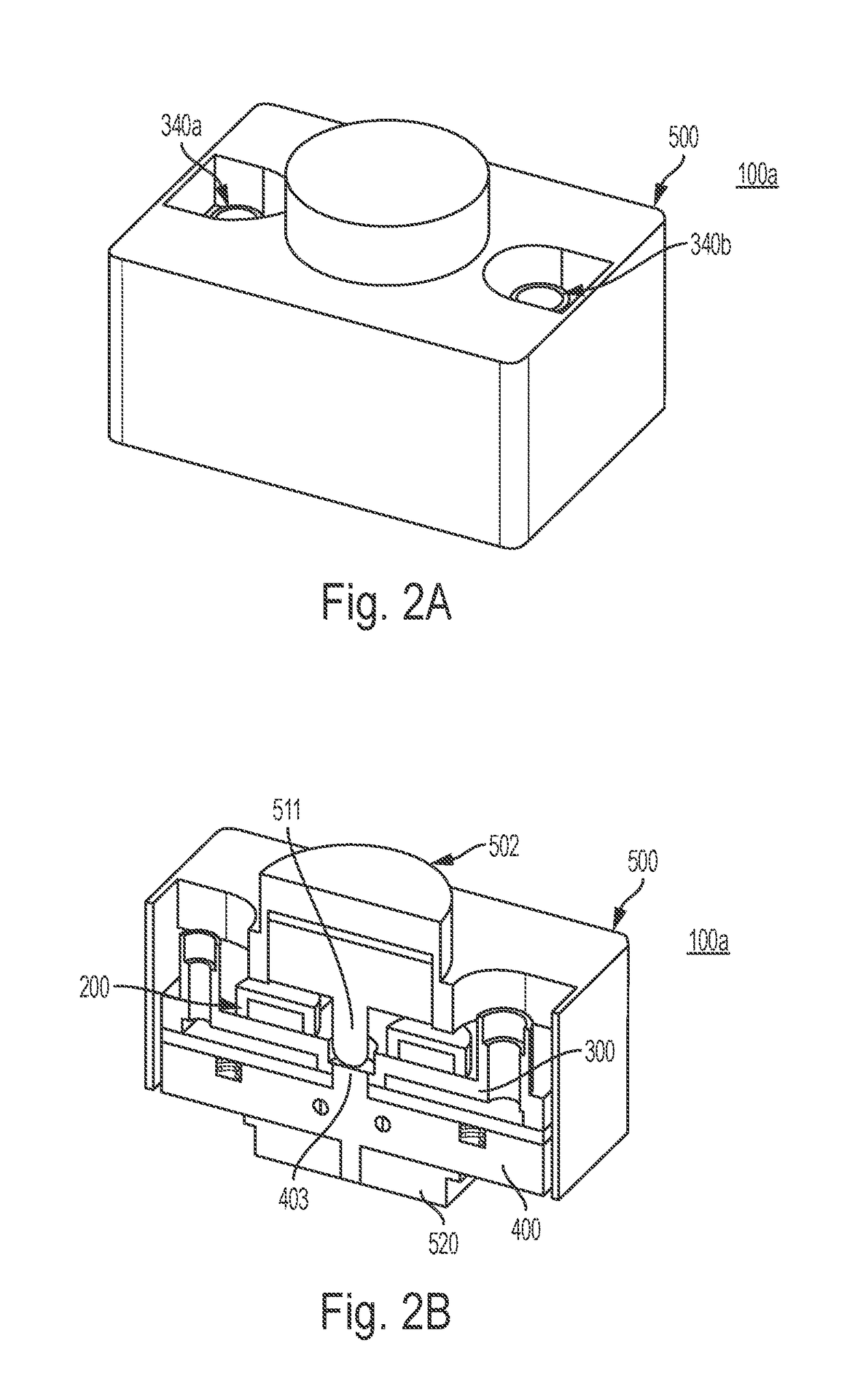
[0052]Referring now to the various figures of the drawing wherein like reference characters refer to like parts, there is shown in FIG. 1 a schematic view illustrating the functional elements comprising a thermal control unit 100 according to the present invention and in particular the relationship of the thermal clutch 200 to the cooling and heating mechanisms 300, 400 of such a thermal control unit. Such a thermal control unit 100 is particularly configured so as to selectively heat and cool a device under test (DUT) 10. While the following may describe the DUT 10 as an integrated circuit (IC) this shall be not limiting as it is within the scope of the present invention for the DUT 10 to comprise a silicon wafer including a plurality or a multiplicity of such ICs, IC packages and other electronic devices for which testing under different temperatures (hot or cool) are contemplated.

[0053]In more particular aspects, a thermal control unit 100 is configured and arranged so as to sele...


PUM


Abstract

Featured are devices, systems and methods for testing an electronic device, such as an integrated chip. Such a testing method includes disposing a thermal clutch between a variable heat sink that absorbs heat energy and a heat source member that selectively delivers heat energy. When the thermal clutch is operated in a first manner the thermal clutch thermally couples the variable heat sink to the electronic device under test (DUT) and when operated in the second manner, the thermal clutch thermally de-couples the variable heat sink from the DUT. Also, when the thermal clutch is operated in the second manner, the heat source member is thermally coupled to the DUT and is operated so as to produce heat energy which is thus provided to the thermally coupled DUT.

Description

FIELD OF INVENTION[0001]The present invention relates to methods, systems and devices for testing of an electronic device such as an integrated chip (IC) that controls the temperature of the electronic device during such testing. More particularly the present invention relates to methods, systems and devices that embody a thermal clutch that thermally couples a cooling member to the electronic device, more specifically an IC, under certain test conditions and that under other test conditions thermally de-couples the electronic device or IC from the cooling member and so the electronic device can thereafter be heated for testing under such temperature conditions.BACKGROUND OF THE INVENTION[0002]Electronic devices including integrated chips (ICs) undergo various forms of testing during the development of such a device as well as a part of the manufacturing process for such a device. Such developmental testing can include testing to determine the suitability or capability of the device...

Claims


Application Information

Patent Timeline
Patent Type & Authority Patents(United States)
IPC IPC(8): G01R31/28G01R1/04H01L23/42G01R31/26H01L23/34
CPCG01R31/2874G01R1/0458H01L23/42G01R31/2891H01L23/345G01R31/26G05D23/20H01L22/10G01R31/2875G01R31/2877
Inventor LOPEZ, CHRISTOPHER A.DAVIS, RICK A.
Owner LTI HLDG INC
Learn More