
Hybrid vehicle

a hybrid vehicle and hybrid technology, applied in the field of hybrid vehicles, can solve the problems of long time to increase the possibility of relatively significant torque of the second motor, and the long time to increase the rotational speed of the engine, so as to prevent torque (regenerative torque), the effect of rapid increase of the electric power consumption of the first motor and quick increase of the engine rotational speed

Active Publication Date: 2018-03-20
TOYOTA JIDOSHA KK
View PDF22 Cites 3 Cited by
  • Summary
  • Abstract
  • Description
  • Claims
  • Application Information

AI Technical Summary

Benefits of technology

The invention provides a hybrid vehicle that prevents the vehicle from sliding down and increasing the speed of the engine takes a long time. The vehicle has a second motor that is controlled to increase the engine's rotational speed quickly when sliding down is detected. The engine is started and driven by the first motor to increase the electric power consumption of the first motor. The second motor is controlled to limit the torque it generates, which prevents it from being significantly limited. This allows the vehicle to travel at a faster speed during sliding down. The electronic control unit can also protect the battery by not executing the drive control when the battery voltage is low or the battery charge is low.

Problems solved by technology

At this time, in the case where the engine is started after detection of the sliding down, it takes long time to increase a rotational speed of the engine, and thus it may take long time to increase the electric power consumption of the first motor.
In the case where permissible charge electric power of the battery is relatively large, a possibility that torque from the second motor is relatively significantly limited (limited to a value whose absolute value is relatively small) is low even when it takes long time to increase the electric power consumption of the first motor.
However, in the case where the permissible charge electric power is relatively small, the torque from the second motor may be relatively significantly limited.
Thus, a sliding down speed of the vehicle may become relatively large.

Method used


Image

  • Hybrid vehicle
  • Hybrid vehicle
  • Hybrid vehicle

Examples


Embodiment Construction

[0014]An embodiment of the invention will be described with reference to the drawings.

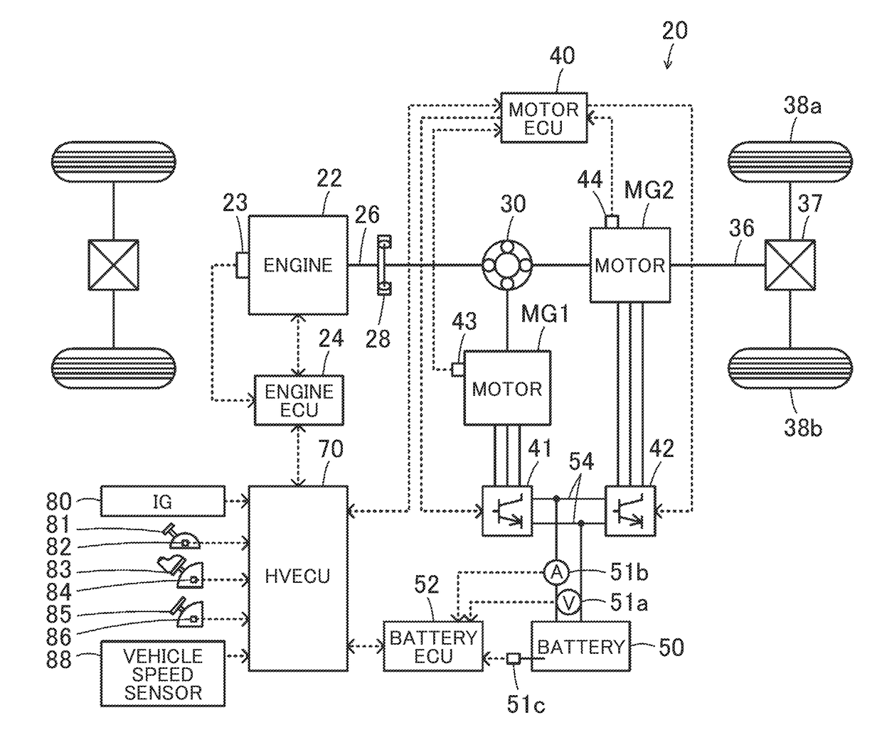
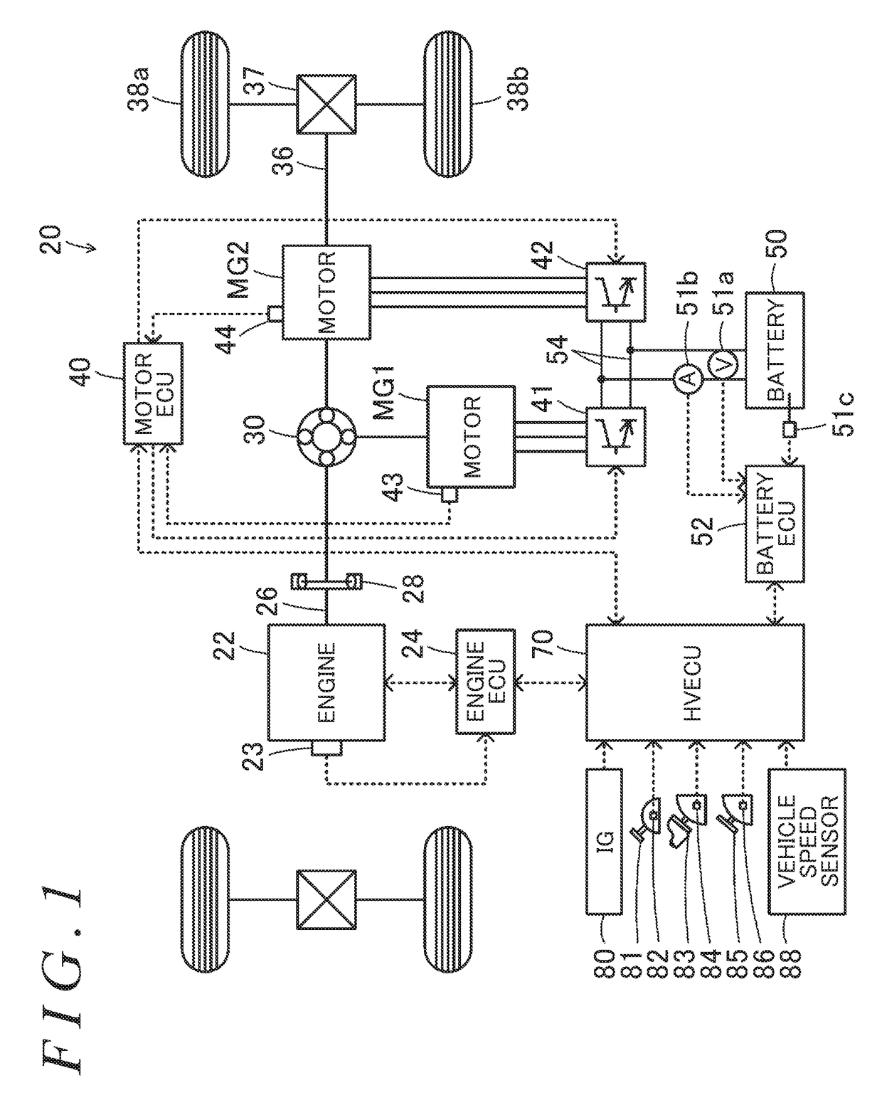
[0015]FIG. 1 is a configuration diagram that schematically shows a configuration of a hybrid vehicle 20 according to the embodiment of the invention. As shown in FIG. 1, the hybrid vehicle 20 of the embodiment includes an engine 22, a planetary gear 30, motors MG1, MG2, inverters 41, 42, a battery 50, and a hybrid electronic control unit (hereinafter referred to as an “HVECU”) 70.

[0016]The engine 22 is configured as an internal combustion engine that outputs power by using fuel such as gasoline or diesel fuel. An operation of this engine 22 is controlled by an engine electronic control unit (hereinafter referred to as an “engine ECU”) 24.

[0017]Although not shown, the engine ECU 24 is configured as a microprocessor that includes a Central Processing Unit (CPU) as a central component, and further includes, in addition to the CPU, a Read-Only Memory (ROM) that stores a processing program, a Random-Acc...


PUM


Abstract

In a hybrid vehicle, an electronic control unit is configured to: control an engine such that the engine is started and a self-sustained operation is performed in a case where i) torque for forward traveling is output from a second motor, ii) sliding down of the vehicle is tentatively detected before the sliding down is detected, and iii) permissible charge electric power is equal to or smaller than first prescribed electric power and rotation of the engine is in a stopped state; and execute drive control such that fuel injection is stopped and the engine is driven by a first motor at a rotational speed larger than that before the sliding down is detected in a case where i) the sliding down is detected thereafter and ii) the permissible charge electric power is equal to or smaller than second prescribed electric power.

Description

INCORPORATION BY REFERENCE[0001]The disclosure of Japanese Patent Application No. 2015-174614 filed on Sep. 4, 2015 including the specification, drawings and abstract is incorporated herein by reference in its entirety.BACKGROUND OF THE INVENTION1. Field of the Invention[0002]The invention relates to a hybrid vehicle.2. Description of Related Art[0003]It has been suggested that, in an electric vehicle that includes a traveling generator motor; a high-voltage battery connected to the traveling generator motor via a power line; and an electrical load (e.g., a DC-DC converter or a compressor of an air conditioner) connected to the power line, the electrical load is actuated at a time when sliding down of the vehicle is detected during output of torque from the generator motor (for example, see Japanese Patent Application Publication No. 2008-193772 (JP 2008-193772 A)). In this electric vehicle, when the sliding down of the vehicle is detected, electric power that is generated by regene...

Claims


Application Information

Patent Timeline
Patent Type & Authority Patents(United States)
IPC IPC(8): B60W10/06B60W20/10B60W10/26B60W30/18B60W10/08B60K6/365B60W20/13B60K6/445B60L50/16
CPCB60W20/13B60K6/445B60W10/06B60W10/08B60W10/26B60W20/10B60W30/18118B60K6/365Y10S903/93B60W2510/083B60W2510/244B60W2710/0644B60W2710/244B60Y2200/92Y02T10/7258Y10S903/91B60W20/40B60W2520/10B60W2710/083B60W2710/0666Y02T10/62Y02T10/72
Inventor SHIMAKAMI, SHINICHI
Owner TOYOTA JIDOSHA KK
Learn More