
Method for detecting occlusion areas

a detection method and occlusion area technology, applied in the field of image processing, can solve problems such as artifacts that may occur in temporal interpolation, and achieve the effect of reducing the computation complexity of image processing and improving efficiency

Active Publication Date: 2018-03-13
XUESHAN TECH INC
View PDF9 Cites 3 Cited by
  • Summary
  • Abstract
  • Description
  • Claims
  • Application Information

AI Technical Summary

Benefits of technology

The method effectively reduces computational complexity and enhances the accuracy of occlusion detection, preventing artifacts in interpolated frames by accurately identifying occlusion areas through block-based analysis.

Problems solved by technology

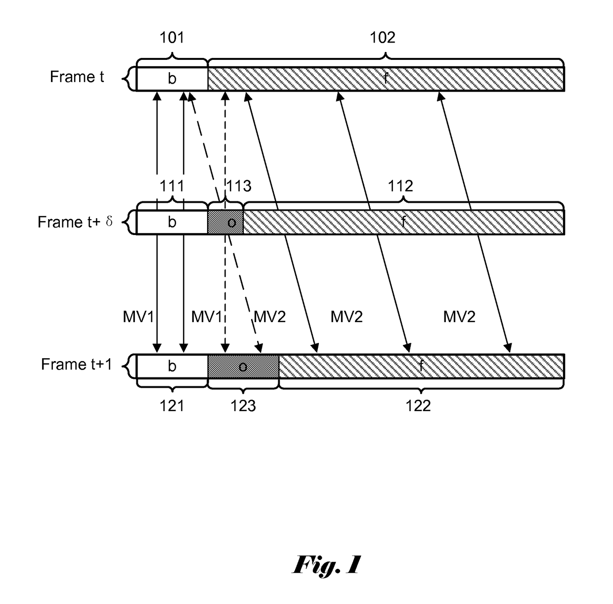
Therefore, special care must be taken in addressing the occlusion problem, otherwise artifacts may occur in temporal interpolation.

Method used


Image

  • Method for detecting occlusion areas
  • Method for detecting occlusion areas
  • Method for detecting occlusion areas

Examples


Embodiment Construction

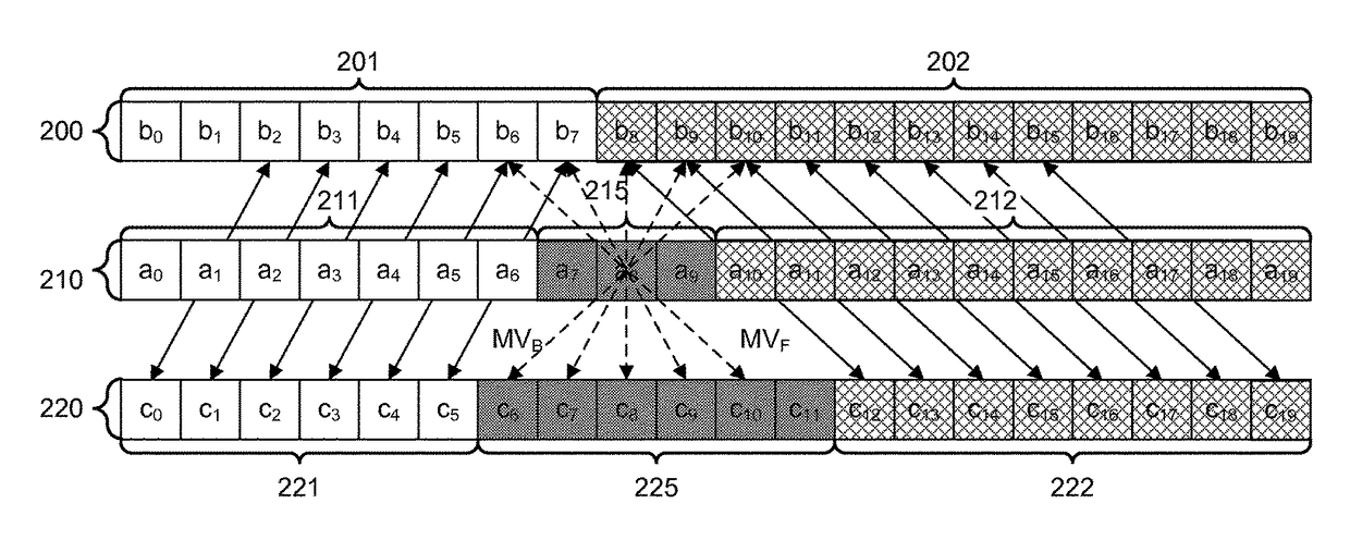
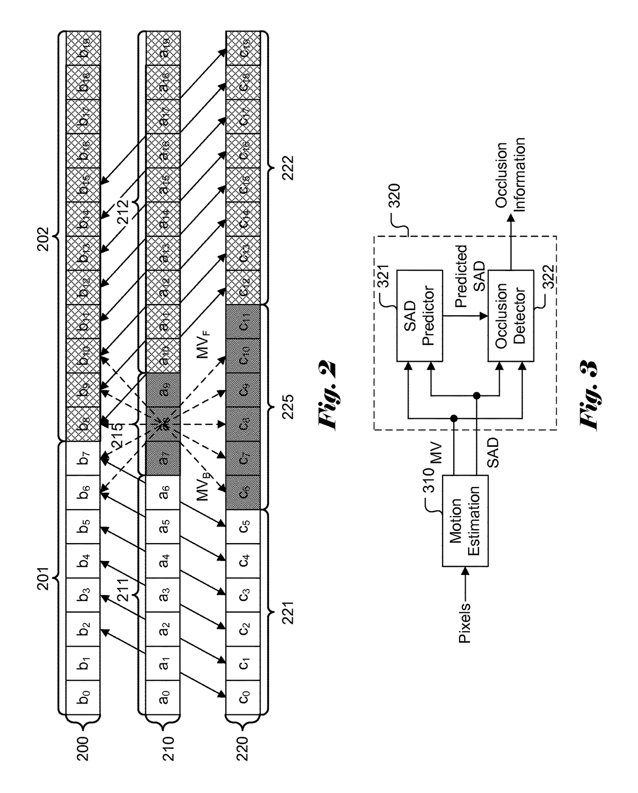
[0024]In the present invention, a block-based method is developed to detect occlusion areas of an image based on two neighboring images. The current image may be an existing image or an image to be interpolated between two neighboring images. Each block of the current image is processed to determine whether it is an occlusion block or not. An occlusion block is referred to a block of pixels that contains one or more occluded pixels. In another word, at least one pixel of the occlusion block is located in the occlusion areas of the image.

[0025]FIG. 2 illustrates an example of matched blocks determined by bidirectional motion estimation performed on two neighboring frames of one interpolated frame according to an embodiment of the present invention. Frame 200 and frame 220 are two consecutive pictures captured, where frame 220 corresponds to a later frame in time than frame 200. Frame 200 comprises a background area shown by area 201 and a foreground area shown by area 202. Frame 220 ...


PUM


Abstract

A method and apparatus for occlusion area detection based on block difference associated with a motion vector and a predicted block difference are disclosed. For each current block of a frame, motion estimation is performed based on a temporally previous frame and a temporally subsequent frame. Based on the motion vector derived, two reference blocks of the current block are located in the temporally neighboring frames. The block difference between these two reference blocks is calculated for the current block. By comparing the block difference with a predicted block difference of the current block, the current block is determined to be an occlusion block or not accordingly. The predicted block difference is updated by averaging the block difference of neighboring blocks in a non-motion boundary area.

Description

FIELD OF THE INVENTION[0001]The present invention relates to image processing. In particular, the present invention relates to detecting occlusion areas in pictures of a video sequence.BACKGROUND[0002]Occlusion areas are parts of a scene which are visible in one frame and become invisible in a neighboring frame of multiple consecutive images due to blockage by foreground object(s). Each of the consecutive images can be a picture captured by imaging system or an interpolated image based on captured pictures. For consecutive images captured by a camera, the presence of the occlusion areas is caused by the changing of relative position between the objects and the camera. When parts of the image become invisible, at least a portion of a background object is covered by a foreground object located closer to the camera due to the projection. Vice versa, the foreground object is located farther away from the camera in the scene and parts of the background become uncovered. The parts of the ...

Claims


Application Information

Patent Timeline
Patent Type & Authority Patents(United States)
IPC IPC(8): H04N7/12H04N5/14H04N19/553H04N7/01
CPCH04N5/145H04N19/553H04N7/0142H04N7/014
Inventor FANG, HUNG-CHICHANG, FANG-CHEN
Owner XUESHAN TECH INC
Learn More