
System architecture for combined static and pass-by processing

a system architecture and pass-by technology, applied in the field of system architecture and processing substrates, can solve the problems of large footprint of the processing machine, large amount of space required, and high cost, and achieve the effect of reducing the speed of the carrier

Active Publication Date: 2018-03-13
INTEVAC
View PDF23 Cites 13 Cited by
  • Summary
  • Abstract
  • Description
  • Claims
  • Application Information

AI Technical Summary

Benefits of technology

[0011]Embodiments of the present invention provide for a substrate processing system which enables combined static and pass-by processing. Embodiments of the invention also provide simplified system construction.
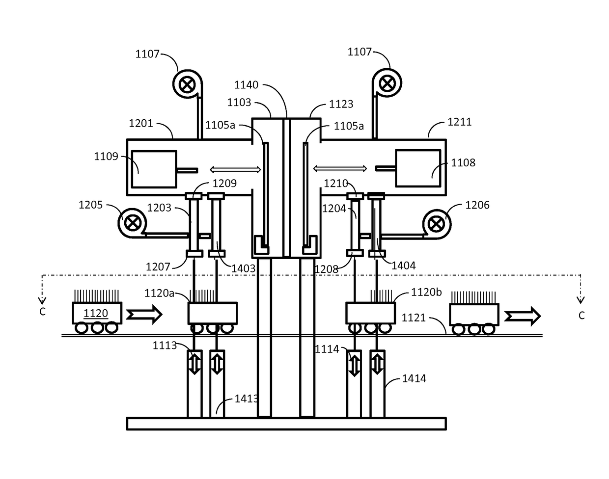
[0013]According to other aspects of the invention, a system architecture is provided, which reduces footprint size. The system is constructed such that the substrates are processed therein vertically, and each chamber has a processing source attached to one sidewall thereof, wherein the other sidewall backs to a complementary processing chamber. According to one aspect, the chamber body is milled from a single block of metal, e.g., aluminum, wherein the block is milled from both sides, such that a partition wall remains and separates each two complementary processing chambers.
[0015]According to other embodiments, a processing chamber body is disclosed, defining a plurality of processing stations, and comprising: a single chamber body machined out of a single block of metal to define therein a first, second, third, and fourth processing stations; a first substrate transport passage machined out of the single block of metal to traverse the first and second processing stations; a second substrate transport passage machined out of the single block of metal to traverse the third and fourth processing stations; and a wall being common to and separating the first and third processing stations and further being common to and separating the second and fourth processing stations, so as to prevent fluid communication between the first and third processing stations and between the second and fourth processing stations. A first set of conveyor wheels enables substrate transport from the first processing station to the second processing station, and a second set of conveyor wheels enables substrate transport from the fourth processing station to the third processing station.
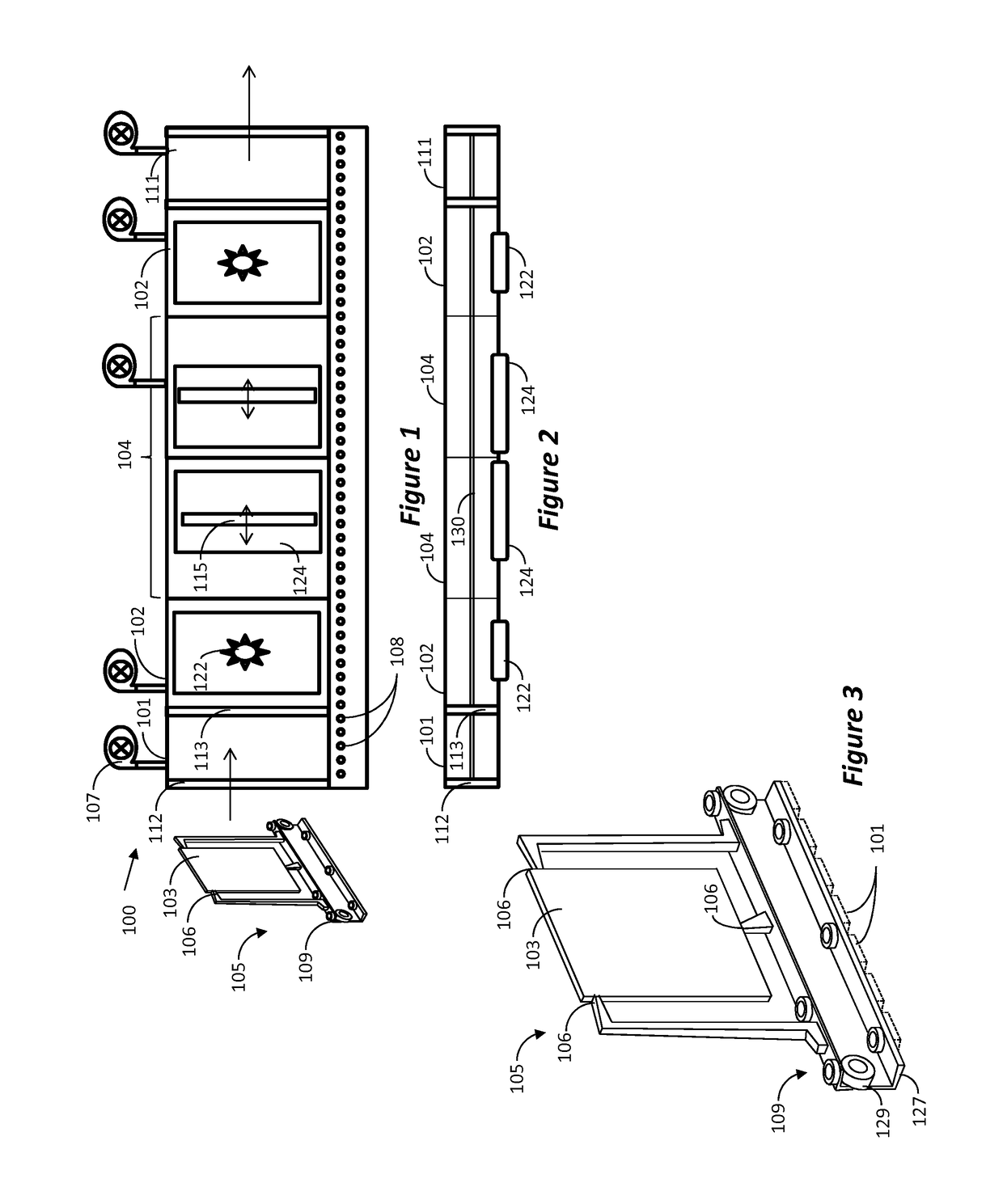
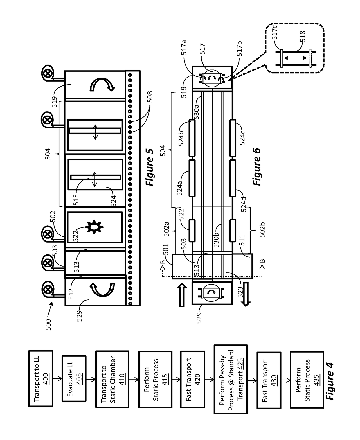
[0018]Also, a method of operation is provided for a system having a static processing chamber and a pass-by processing chamber, the method for processing substrates, comprises: introducing the substrate into a vacuum environment; loading the substrate onto a carrier; transporting the carrier into the static processing chamber and holding the carrier in its position during processing inside the static processing chamber; once processing inside the static processing chamber is completed, transporting the carrier into the pass-by processing chamber at transport speed, until the carrier reaches a position behind a preceding carrier positioned within the pass-by processing chamber; once the carrier reaches the position behind the preceding carrier, reducing the speed of the carrier to thereby continue transporting the carrier inside the pass-by processing chamber at a processing speed which is slower than the transport speed.

Problems solved by technology

Substrate processing, such as the fabrication of magnetic disks, touch-screens, etc., is a complex and complicated process.
Machines for processing substrates usually have a large footprint, and require a significant amount of space to operate.
Additionally, the machines need to be operated in high-tech clean rooms, which are expensive to build and maintain.
Improving the processing speed is somewhat challenging, since many processing steps have a minimum required time that a particular coating must be applied, heated, or cooled in order to properly fabricate a substrate.
However, current systems do not provide workable solution for combining both static and pass-by processing in a single linear system.

Method used


Image

  • System architecture for combined static and pass-by processing
  • System architecture for combined static and pass-by processing
  • System architecture for combined static and pass-by processing

Examples


Embodiment Construction

[0035]The various aspects of the present invention provide for the processing of substrates to fabricated items such as hard disks, ICs, touch screens, etc. The disclosed embodiments illustrate various features, such as combined static and pass-by processing, reduction of footprint, simplified chamber manufacturing, etc. While some of the illustrated embodiments use more than one feature, it should be understood that the features can be implemented independently or in different combinations with various processing systems.

[0036]In one aspect of the invention, combined static and pass-by processing of substrates is enabled. As illustrated in the example of FIG. 1, a substrate processing system 100 comprises a linear series of static processing chambers 102 and pass-by processing chambers 104 for applying various coatings or processes to substrates 103. The substrates are mounted onto carriers 105, as shown in more details in FIG. 3. The carrier 105 makes contact with an outer edge of...


PUM

PropertyMeasurementUnit
widthaaaaaaaaaa
transport speedaaaaaaaaaa
sizeaaaaaaaaaa

Abstract

Disclosed is a substrate processing system which enables combined static and pass-by processing. Also, a system architecture is provided, which reduces footprint size. The system is constructed such that the substrates are processed therein vertically, and each chamber has a processing source attached to one sidewall thereof, wherein the other sidewall backs to a complementary processing chamber. The chamber system can be milled from a single block of metal, e.g., aluminum, wherein the block is milled from both sides, such that a wall remains and separates each two complementary processing chambers.

Description

RELATED CASES[0001]This Application claims priority benefit from U.S. Provisional Application Ser. No. 61 / 580,642, filed on Dec. 27, 2011, the disclosure of which is incorporated herein by reference in its entirety.BACKGROUND[0002]1. Field[0003]This disclosure relates to a system architecture and method for handling and processing substrates such as magnetic disks, touch-screens, etc., and more specifically, to a system and method for improved process flow of a substrate carrier in a substrate processing system using combined static and pass-by processing.[0004]2. Related Art[0005]Substrate processing, such as the fabrication of magnetic disks, touch-screens, etc., is a complex and complicated process. Large, customized equipment is required to carry out the numerous unique steps of pre-heating, coating a substrate with multiple layers, then annealing and / or cooling the substrate. Machines for processing substrates usually have a large footprint, and require a significant amount of ...

Claims


Application Information

Patent Timeline
Patent Type & Authority Patents(United States)
IPC IPC(8): C23C14/34C23C14/50C23C14/56
CPCC23C14/34C23C14/50C23C14/566C23C14/568H01J37/32889H01J37/3488H01J37/32899
Inventor LEAHEY, PATRICKLAWSON, ERICLIU, CHARLESBLUCK, TERRYFAIRBAIRN, KEVIN P.RUCK, ROBERT L.HARKNESS, IV, SAMUEL D.
Owner INTEVAC
Learn More