
Communication device, communication system, method for determining path, and program

a communication system and path technology, applied in the field of communication systems, can solve the problems of network failure to transfer data, path failure recovery time based on a restoration scheme often longer than 50 milliseconds

Active Publication Date: 2018-03-06
NEC CORP
View PDF18 Cites 0 Cited by
  • Summary
  • Abstract
  • Description
  • Claims
  • Application Information

AI Technical Summary

Benefits of technology

Enables quick and reliable path switching between multiple paths, ensuring continuous data transfer even when both the working and backup paths fail, and allows for efficient maintenance by temporarily moving data to backup paths.

Problems solved by technology

In a communication network, especially in a transport network forming its core, one of the most important issues is to improve reliability.
Thus, a network will fail to transfer data when a failure occurs at any node or link.
Thus, a path failure recovery time based on a restoration scheme is often longer than 50 milliseconds, which is the time required in a transport network as a path failure recovery time.

Method used


Image

  • Communication device, communication system, method for determining path, and program
  • Communication device, communication system, method for determining path, and program
  • Communication device, communication system, method for determining path, and program

Examples


first embodiment

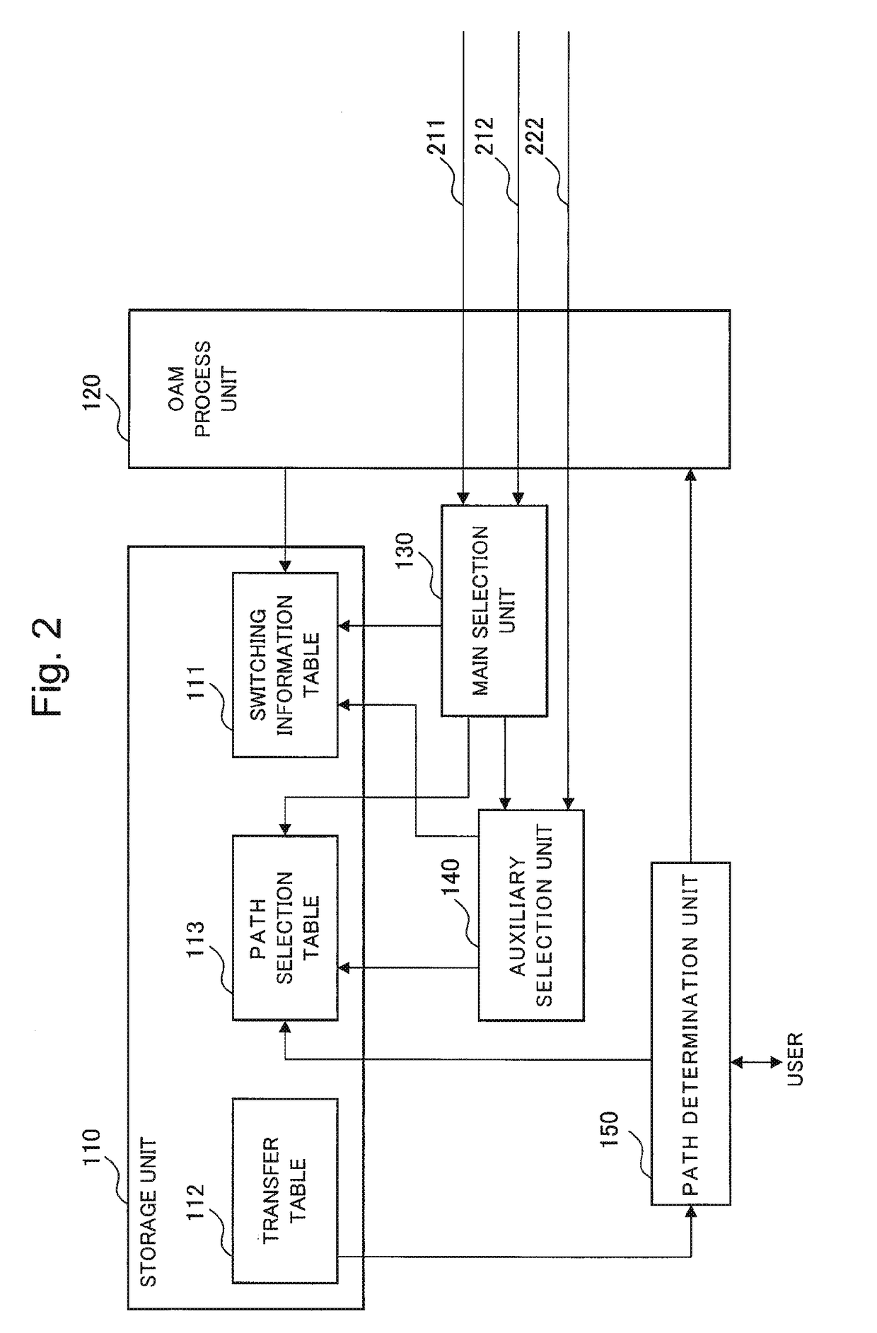
[0052]FIG. 2 is a schematic block diagram illustrating a configuration of a communication device 100 according to a first embodiment of the present invention.

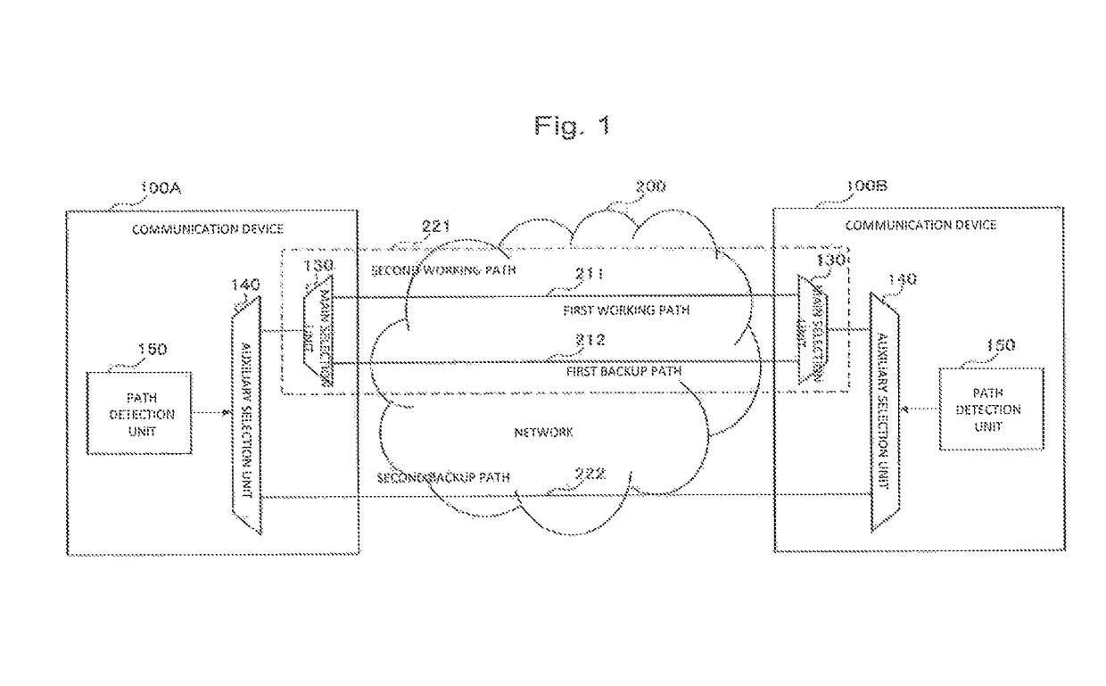
[0053]The communication device 100 includes a storage unit 110, an OAM (operation admission and maintenance) process unit 120, a main selection unit 130, an auxiliary selection unit 140, and a path determination unit 150. The communication devices 100A and 100B illustrated in the basic configuration in FIG. 1 are configured similarly to the communication device 100 shown in FIG. 2.

[0054]The storage unit 110 stores a switching information table 111, a transfer table 112, and a path selection table 113.

[0055]FIG. 3 represents an example of the switching information table 111 according to the first embodiment of the present invention.

[0056]The switching information table 111 stores identification information on a switching group and information about the group's associated members including path, path attribute, internal status, a...

second embodiment

[0096]A second embodiment of the present invention will now be explained.

[0097]FIG. 9 is a schematic block diagram illustrating a configuration of a communication system according to the second embodiment of the present invention.

[0098]Unlike the first embodiment, a network 200 in a communication system according to this embodiment includes a plurality of candidate paths 230 as candidates for a second backup path 222. In addition, a communication device 100 includes a backup path selection unit 160 which selects the best performance candidate path 230 from the plurality of candidate paths 230 as a second backup path 222.

[0099]FIG. 10 is a schematic block diagram illustrating a configuration of the communication device 100 according to the second embodiment of the present invention.

[0100]In addition to the configuration of the first embodiment, the communication device 100 according to the second embodiment further includes a plurality of auxiliary selection units 140 and a performan...


PUM


Abstract

A communication device communicates with a counterpart device via a working path or any of a plurality of backup paths. The communication device includes: a plurality of selection units which select either one of two paths, the plurality of selection units including a main selection unit and an auxiliary selection unit being different from the main selection unit; and a path determination unit which determines a path selected by one of the plurality of selection units which has last performed path selection to be a path to be used for communicating with the counterpart device. The main selection unit selects one path from between the working path and one of the plurality of backup paths. The auxiliary selection unit selects one path from between a path selected by one selection unit of the plurality of selection units and one of the plurality of backup paths, the one selection unit being different from the auxiliary selection unit.

Description

CROSS-REFERENCE TO RELATED PATENT APPLICATIONS[0001]This application is a National Stage Entry of International Application No. PCT / JP2013 / 064734, filed May 28, 2013, which claims priority from Japanese Patent Application No. 2012-165748, filed Jul. 26, 2012. The entire contents of the above-referenced applications are expressly incorporated herein by reference.TECHNICAL FIELD[0002]The present invention relates to a communication device, a communication system, a method for determining a path, and a program, which are for communicating with a counterpart device via a working path or any of a plurality of backup paths.BACKGROUND ART[0003]Due to the recent upsurge in data traffic, communication networks have increasingly large transfer capacities. In a communication network, especially in a transport network forming its core, one of the most important issues is to improve reliability.[0004]A transport network accomplishes data communications using a traffic transfer path which is made...

Claims


Application Information

Patent Timeline
Patent Type & Authority Patents(United States)
IPC IPC(8): H04L12/24H04L12/707H04L12/703H04L12/28H04L45/247H04L45/28H04L45/24
CPCH04L41/0668H04L12/2863H04L45/22H04L45/28H04L41/06Y02D50/30Y02D30/50
Inventor CUI, ZHENLONGTAKAGI, KAZUOSAKURAI, AKIRA
Owner NEC CORP
Learn More