
Ring protocol for low latency interconnect switch

a low-latency, interconnection switch technology, applied in the direction of memory architecture accessing/allocation, instruments, computing, etc., can solve the problems of increasing the latency of point-to-point communication via virtual links implemented via such cross-bar interconnection, limited computer workload, and limited practical limit to maximum bus speed

Inactive Publication Date: 2018-03-06
INTEL CORP
View PDF28 Cites 0 Cited by
  • Summary
  • Abstract
  • Description
  • Claims
  • Application Information

AI Technical Summary

Benefits of technology

The ring interconnect architecture significantly reduces latency and improves scalability by enabling efficient data transfer between CPU sockets, maintaining cache coherence and supporting high-performance communication in multi-core and multi-processor systems.

Problems solved by technology

As a result, computer workloads were often limited by interconnect bottlenecks rather than processor speed.
Although parallel buses support the transfer of a large amount of data (e.g., 32 or even 64 bits under PCI-X) with each cycle, their clock rates are limited by timing skew considerations, leading to a practical limit to maximum bus speed.
As the number of sockets and cores increase, latency for point-to-point communication via virtual links implemented via such cross-bar interconnect likewise increases.

Method used


Image

  • Ring protocol for low latency interconnect switch
  • Ring protocol for low latency interconnect switch
  • Ring protocol for low latency interconnect switch

Examples


Embodiment Construction

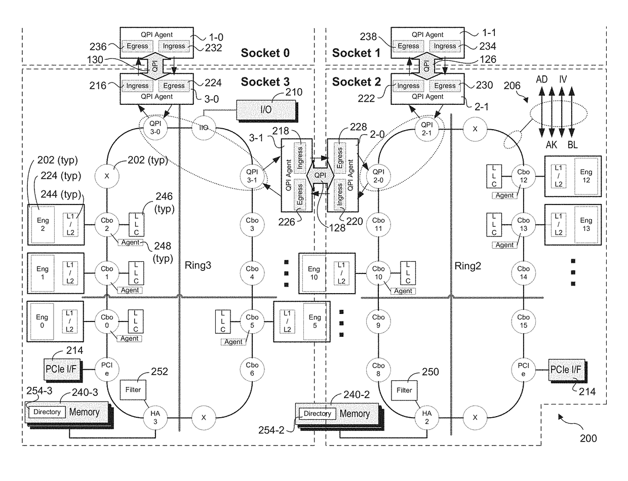
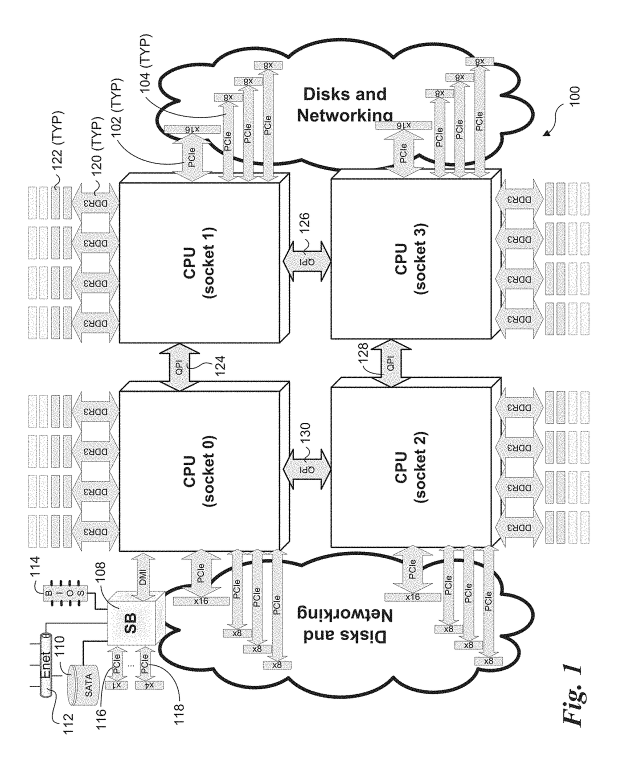
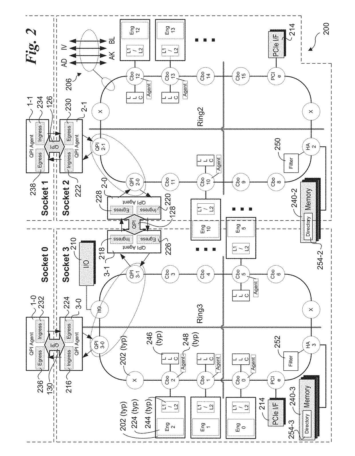
[0021]Embodiments of methods, systems, and apparatus for implementing low latency interconnect switches and associated protocols are described herein. In the following description, numerous specific details, such as implementations employing QPI interconnects, are set forth to provide a thorough understanding of embodiments of the invention. One skilled in the relevant art will recognize, however, that the invention can be practiced without one or more of the specific details, or with other methods, components, materials, etc. In other instances, well-known structures, materials, or operations are not shown or described in detail to avoid obscuring aspects of the invention.

[0022]Reference throughout this specification to “one embodiment” or “an embodiment” means that a particular feature, structure, or characteristic described in connection with the embodiment is included in at least one embodiment of the present invention. Thus, the appearances of the phrases “in one embodiment” or...


PUM


Abstract

Methods, systems, and apparatus for implementing low latency interconnect switches between CPU's and associated protocols. CPU's are configured to be installed on a main board including multiple CPU sockets linked in communication via CPU socket-to-socket interconnect links forming a CPU socket-to-socket ring interconnect. The CPU's are also configured to transfer data between one another by sending data via the CPU socket-to-socket interconnects. Data may be transferred using a packetized protocol, such as QPI, and the CPU's may also be configured to support coherent memory transactions across CPU's.

Description

RELATED APPLICATIONS[0001]The present application is a continuation of U.S. patent application Ser. No. 13 / 994,792, filed on Jul. 24, 2014, entitled “RING PROTOCOL FOR LOW LATENCY INTERCONNECT SWITCH”, which is a U.S. National Phase Application under 35 U.S.C. Section 371 of International Application No. PCT / US2011 / 062311, filed on Nov. 29, 2011, entitled “RING PROTOCOL FOR LOW LATENCY INTERCONNECT SWITCH”, which is hereby incorporated herein by reference in its entirety and for all purposes.FIELD OF INVENTION[0002]The field of invention relates generally to computer system interfaces and, more specifically but not exclusively relates to techniques for facilitating low latency communication between components and agents on separate sockets.BACKGROUND INFORMATION[0003]Computer systems typically employ one or more interconnects to facilitate communication between system components, such as between processors and memory. Interconnects and / or expansion interfaces may also be used to sup...

Claims


Application Information

Patent Timeline
Patent Type & Authority Patents(United States)
IPC IPC(8): G06F13/40G06F13/16G06F13/42
CPCG06F13/4022G06F13/4282G06F13/161G06F12/0292G06F12/0813G06F12/0831G06F2212/1024G06F2212/2542
Inventor BLANKENSHIP, ROBERT G.SANTHANAKRISHNAN, GEEYARPURAM N.LIU, YEN-CHENGFAHIM, BAHAASRINIVASA, GANAPATI N.
Owner INTEL CORP
Learn More