
Inter-ring fairness control method and rpr node device

a control method and fairness technology, applied in the field of communication networks, can solve the problems of impaired communication traffic fairness and inability to implement the fairness defined in the rpr

Inactive Publication Date: 2008-10-02
NEC CORP
View PDF9 Cites 1 Cited by
  • Summary
  • Abstract
  • Description
  • Claims
  • Application Information

AI Technical Summary

Benefits of technology

[0017]The present invention is made in such a background, and an object thereof is to provide an RPR node device, a fairness control method, and an RPR communications system which can guarantee the fairness of communication traffic that is guaranteed within an RPR ring, even at a ring interconnection in a communications network in which a plurality of RPR ring systems are interconnected.

Problems solved by technology

However, IEEE 802.17 does not specify any fairness control to be carried out between RPR rings interconnected.
Therefore the fairness defined in RPR cannot be implemented.
Accordingly, when scaling up a network by interconnecting a plurality of RPR rings to make a big-scale communications network structure, there arises a problem that the fairness of communication traffic is impaired.

Method used


Image

  • Inter-ring fairness control method and rpr node device
  • Inter-ring fairness control method and rpr node device
  • Inter-ring fairness control method and rpr node device

Examples


first exemplary embodiment

1. First Exemplary Embodiment

1.1) Structure of Ring-Interconnecting RPR Node

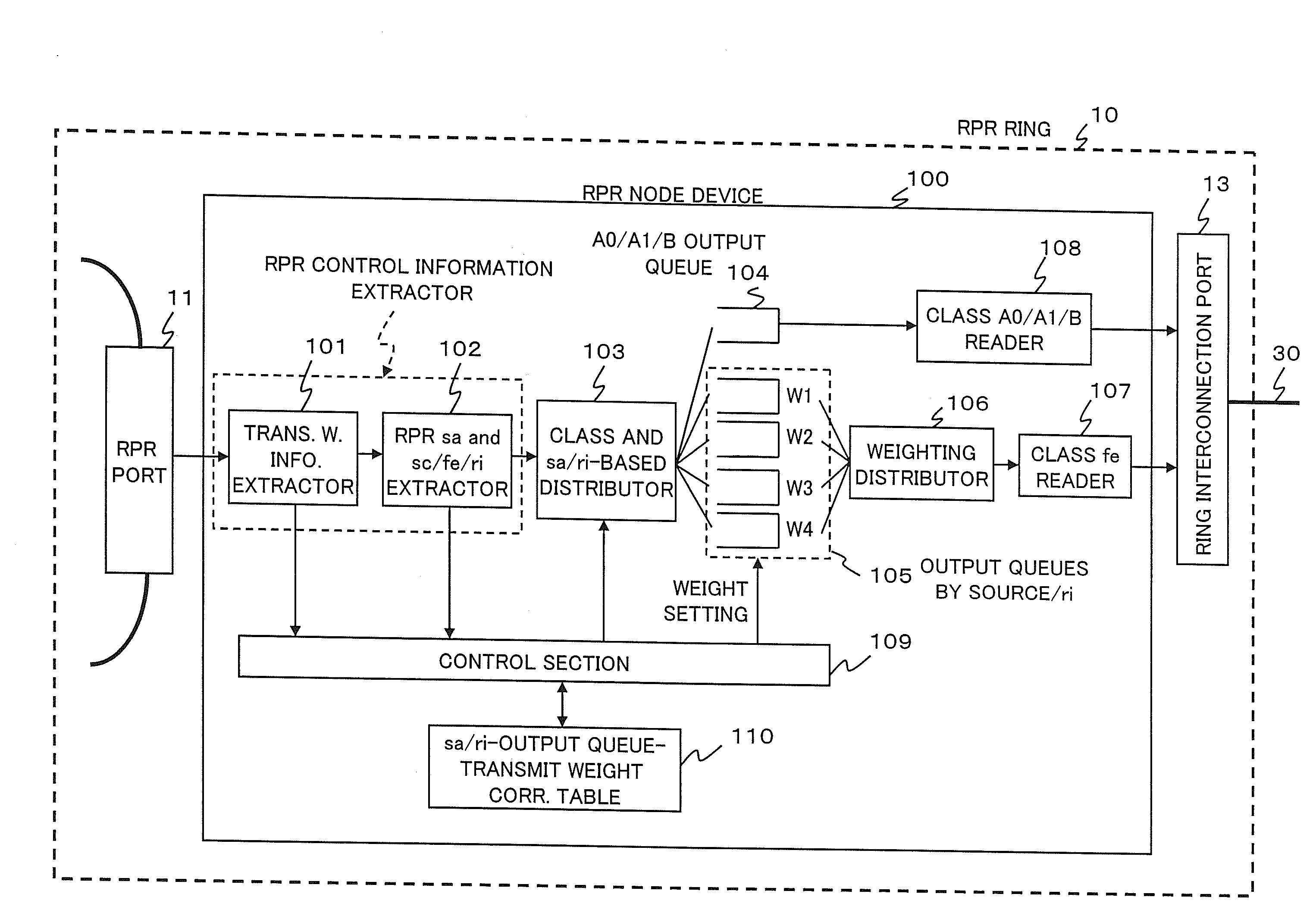
[0043]Referring to FIG. 5, the RPR node device 100 is provided with a RPR control information extractor composed of a transmit weight information extractor 101 and an RPR sa and sc / fe / ri extractor 102, which are called hereinafter a first extractor 101 and a second extractor 102, respectively.

[0044]The RPR node device 100 is further provided with a class and source / ri-based distributor 103, A0 / A1 / b output queue 104, by-source / ri output queues 105, a weighting distributor 106, a class fe reader 107, a class A0 / A1 / B reader 108, a control section 109 and a source / ri-queue-weight correspondence table 110. The first extractor 101 is connected to the RPR port 11, and the class fe reader 107 and the class A0 / A1 / B reader 108 are connected to the ring interconnection port 13.

[0045]The RPR node device 100 receives packets on the communication traffic that are to be transmitted to another network from an RPR port 11. W...

second exemplary embodiment

2. Second Exemplary Embodiment

[0065]A second exemplary embodiment of the present invention will be described. Although the basic configuration of this exemplary embodiment is similar to the above-described first exemplary embodiment, a modification is made to the output queues.

[0066]FIG. 9 shows the configuration of an RPR node device 200 according to the second exemplary embodiment. Referring to FIG. 9, the configuration of the output queues to store communication data according to the first exemplary embodiment is modified to obtain a single output queue, whereby the total quantity of queues is reduced. In the communication traffic on an RPR ring 10, when traffic to be transmitted from the RPR ring 10 to another RPR ring 20 is input to the RPR node device 200, an RPR sa and sc / fe / ri extractor 201 extracts the RPR source address (sa), service class (sc), fairness bit (fe), and ring transmit direction (ri) information from input packets.

[0067]The RPR source address which has been gi...


PUM


Abstract

The fairness of communication traffic guaranteed within an RPR ring is guaranteed also at a ring interconnection. Transmit weight information used for fairness control is extracted from RPR control information in an arrival packet. In addition to this transmit weight information, a source address, a service class, a fairness bit, and a ring transmit direction are also extracted. If the packet has a fairness bit of “0,” the packet is temporarily stored in an output queue by service class. If the packet has a fairness bit of “1,” the packet is weighted by source and ring transmit direction, based on the transmit weight information, and is temporarily stored in an output queue by source and ring transmit direction. Reading of packets from the output queue by service class is performed prior to reading of packets from the output queue by source and ring transmit direction.

Description

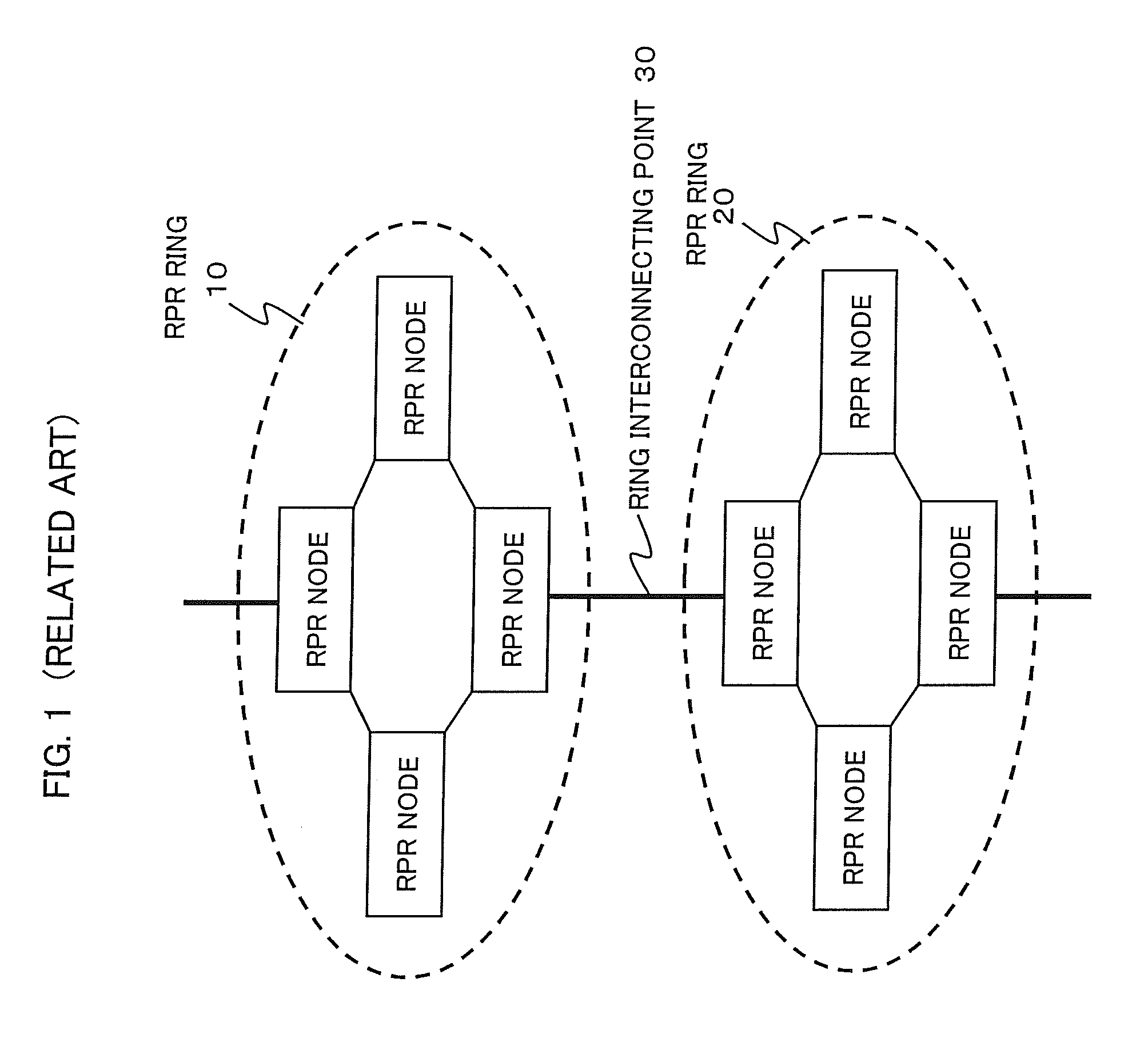
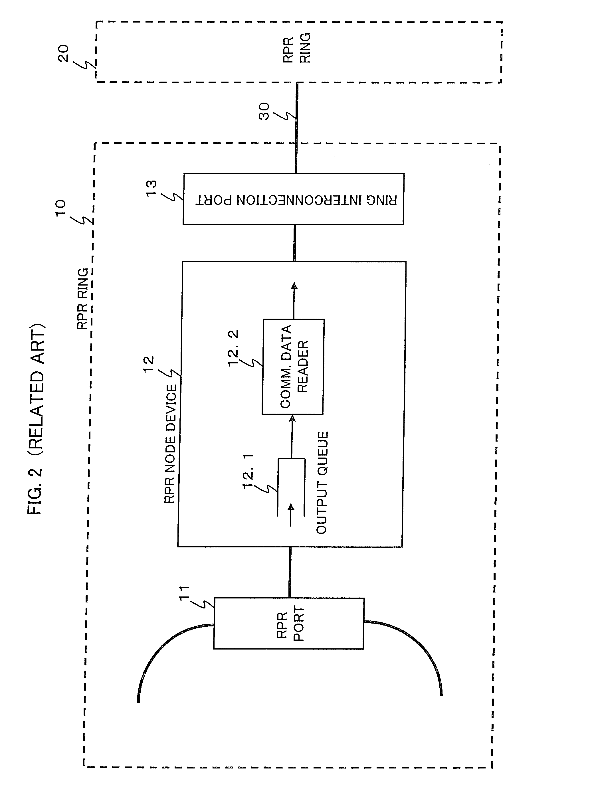
[0001]This application is based upon and claims the benefit of priority from Japanese Patent Application No. 2007-081401, filed on Mar. 27, 2007, the disclosure of which is incorporated herein in its entirety by reference.BACKGROUND OF THE INVENTION[0002]1. Field of the Invention[0003]The present invention relates to a communication network in which a plurality of packet ring networks are interconnected and in particular fairness control techniques in packet transmission between packet ring networks based on RPR (Resilient Packet Ring: IEEE 802.17) protocol or the like.[0004]2. Description of the Related Art[0005]For simplicity, it is assumed that adjacent ring networks (here, two RPR rings) are interconnected, each RPR ring having a plurality of RPR node devices connected in a ring topology.[0006]As shown in FIG. 1, RPR ring 10 and RPR ring 20 are interconnected through a ring interconnecting point 30. Communications between these RPR rings 10 and 20 are performed through the ring ...

Claims


Application Information

Patent Timeline
IPC IPC(8): H04Q7/00H04L12/42
CPCH04L12/42H04L12/437H04L12/5693H04L47/10H04L47/623H04L47/50
Inventor TSUCHIYA, MASAHIKO
Owner NEC CORP
Learn More