Hair trimmer with cutting guide

a hair trimmer and guide technology, applied in the direction of metal working devices, etc., can solve the problems of not enabling unable to enable a user to accurately cut hair in a horizontal line, and difficult for a user to trim hair, especially facial hair

Active Publication Date: 2018-02-27
KONINK PHILIPS ELECTRONICS NV
View PDF23 Cites 0 Cited by
  • Summary
  • Abstract
  • Description
  • Claims
  • Application Information

AI Technical Summary

Benefits of technology

[0005]It would be advantageous to provide a device for cutting hair that substantially alleviates or overcomes at least one of the problems mentioned above.
[0009]The device may further comprise a second cutting guide member pivotally mounted to the first cutting guide member. The second cutting guide member may be provided on an opposite end of the first cutting guide member to the point at which the first cutting guide member is mounted to the support member. Such an embodiment with first and second cutting guide members would afford a user a greater variety of reference guide positions to enable a wider range of hair cutting angles to be achieved.
[0012]The cutting guide may be detachably mounted on the body portion or on the cutting blade. This provides the advantage of flexibility, enabling a user to choose to use the hair cutting device with or without the cutting guide, and so use the cutting guide only when required. Furthermore, the cutting guide may be configured to be attachable to the body portion or cutting blade assembly in a plurality of different orientations. This can allow a user to more easily recreate a style from one side of the body / face to the other.
[0014]The cutting guide may alternatively comprise a first light source to project a first light beam onto a user's skin as said reference line and, the first light source may be moveable so that the angle of the first light beam relative to the cutting blade can be adjusted to the chosen angle. The first light beam may comprise a reference shape to be projected on the user's face, such as circle sector, and the shape may be variable in configuration to vary the reference line thereof, for example to vary the angle of the circle sector. This can provide an easily visible reference line without any guide member physically touching the user's skin / body, and enables the angle of the light beam to be adjusted. The angle of the first light beam relative to the cutting blade may be adjustable within a range of angles that includes zero degrees to the cutting blade assembly (i.e. parallel thereto) or alternatively, may be adjustable within a range of angular positions relative to the cutting blade assembly that excludes being parallel to, or exactly aligned with, the cutting blade assembly.
[0015]The device may further comprise a second light source, which may be fixed relative to the cutting blade, to project a second light beam parallel to the cutting blade such that the first and second light beams intersect to define a cross-hair reference point for a hair cutting operation. Such a pair of reference beams provides the advantage that particular hair or facial features can be aligned with the respective beams and intersection point to further enhance hair cutting accuracy.
[0018]The cutting guide may include a rotary control actuator to control the angular position of the first light source. This could enable easy manipulation of the cutting guide by a user to the desired position.

Problems solved by technology

When using such devices, it can be difficult for a user to trim hair, especially facial hair, with precision in order to create a desired hair style, and to mirror the style from one side of the face to the other.
One problem with the hair cutting / trimming device disclosed in US 2004 / 139615 is that it only enables a user to accurately cut hair in a horizontal line.
Although the light line allows a user to see where the blade will contact his face, the device of this document does not enable a user to accurately cut hair in a desired pattern or style relative to any reference points on the user's face or body, nor does the device provide any means to allow a user to mirror a hair style cut on one side of a user's face to the other side.

Method used


Image

  • Hair trimmer with cutting guide
  • Hair trimmer with cutting guide
  • Hair trimmer with cutting guide

Examples


second embodiment

[0047]Although the device 110 of the invention is shown and described as having two light sources 117, 118 to project two reference beams 119, 121, it is intended within the scope of the invention that a hair cutting device may include just one light source, being an adjustable light source to project an adjustable reference beam at a chosen angle relative to the blade portion 112 of the device, and the second light source 118 that projects a beam on the user's face at a position forwards of, or coincident with where the blade portion 112 contacts the user's face, may be omitted. Furthermore, it is intended within the scope of the invention that in such an embodiment where only a single light source is provided, the beam projected may not necessarily be a straight line, but may comprise another shape having one or more angled surfaces, such as a sector of a circle, so that one line of the sector can be aligned with a reference feature on a user's face / body, and another line of the s...

third embodiment

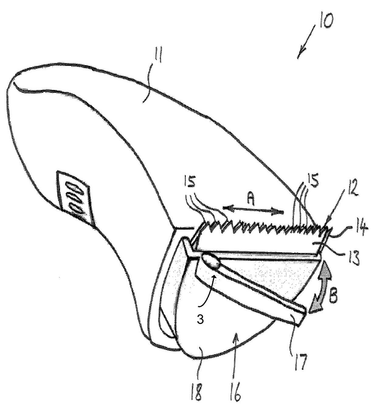
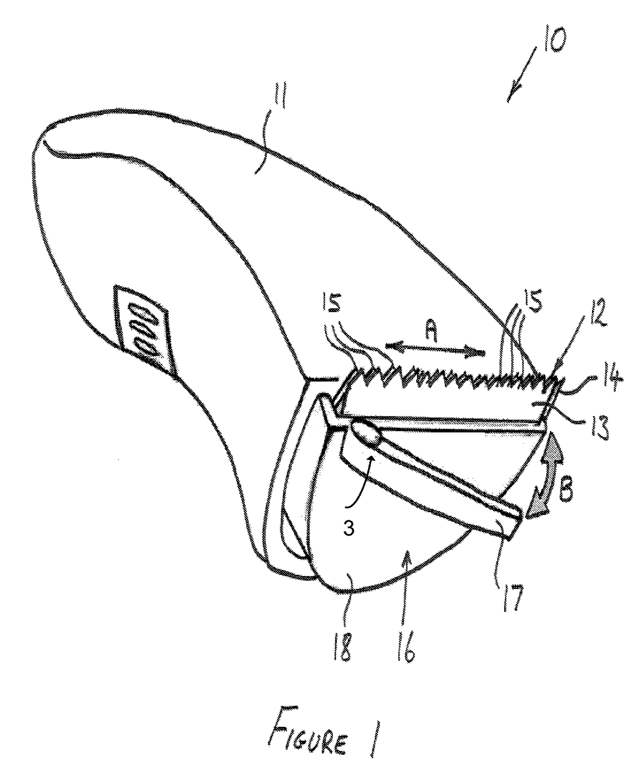
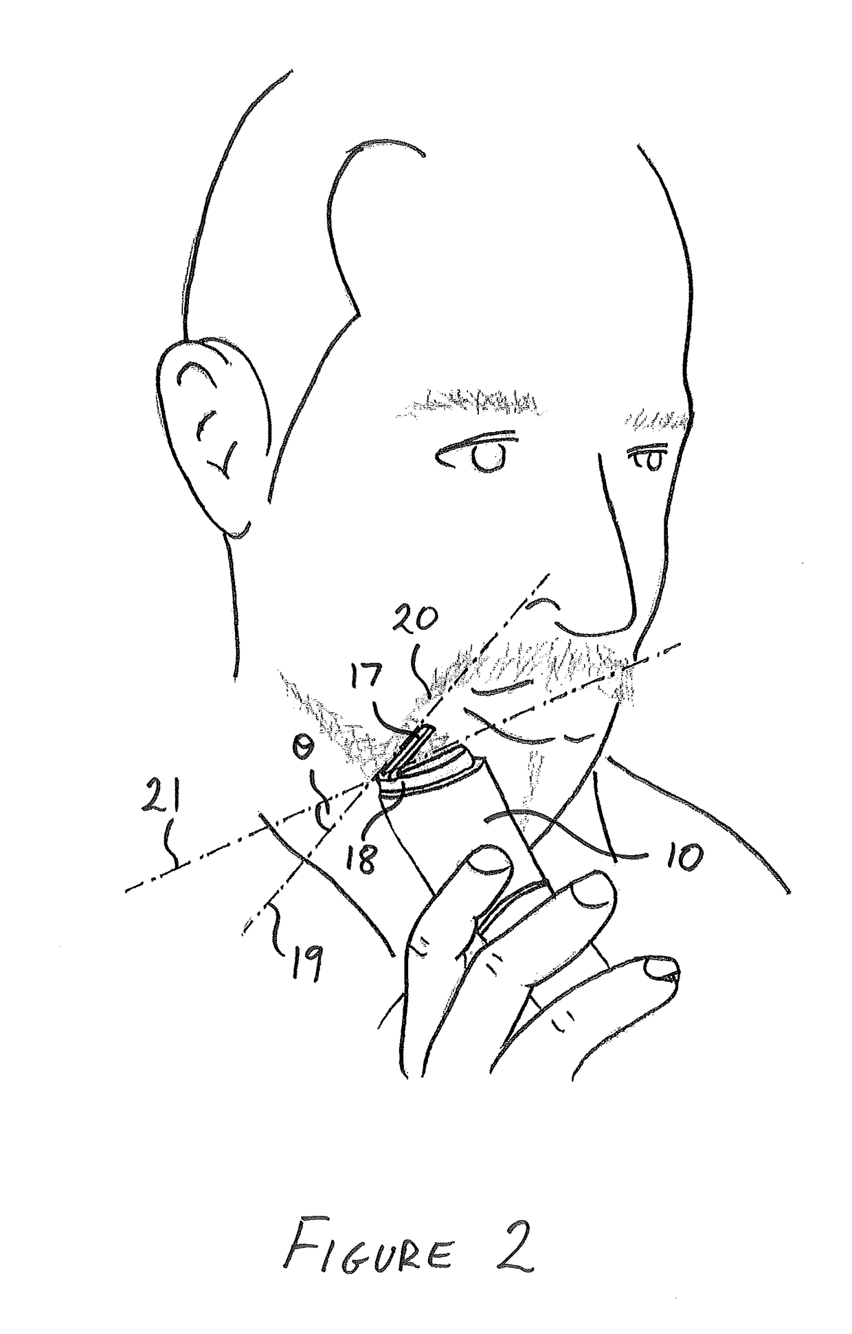
[0048]A device 210 for cutting hair according to the invention is shown in FIGS. 5-9 and comprises a body portion 211 and a blade portion 212. The blade portion 212 comprises a fixed blade plate 213 and moving blade plate 214 as described previously and so a detailed description will not be repeated. A cutting guide 216 is provided which comprises a guide member 217 pivotally mounted to a support plate 218 at a hinge portion 219, and the support plate 218 is detachably held in a holder 220. The holder 220 itself is detachably secured at the end of the device 210 proximate the blade portion 212 (although it is intended within the scope of the invention that the holder 220 may be integrally formed with the device 210). The guide member 217 is configured to pivot towards and away from the support plate 218 about the hinge portion 219, and therefore is pivotable relative to the blade portion 212. The guide member 217 is shown pivoted away from the support plate 218 in FIG. 7.

[0049]The h...

fourth embodiment

[0051]A device 310 for cutting hair according to the invention is shown in FIGS. 10-12 and comprises a body portion 311 and a blade portion 312. The blade portion 312 comprises a fixed blade plate 313 and moving blade plate 314 as described previously and so a detailed description will not be repeated. A cutting guide 316 is provided which is shown in more detail in FIGS. 11 and 12, and comprises a first guide member 317a pivotally mounted to a support plate 318 at a first hinge portion 319a, and a second guide member 317b pivotally mounted by a second hinge portion 319b to the opposite end of the first guide member 317a to the first hinge portion 319a. The support plate 318 is detachably held in a holder 320 which itself is detachably secured at the end of the device 310 proximate the blade portion 312 (although it is intended within the scope of the invention that the holder 320 may be integrally formed with the device 310).

[0052]The first guide member 317a is configured to pivot ...


PUM


Abstract

A hair cutting device (10) comprises a blade portion (12) and an adjustable cutting guide (16) moveable with respect to the blade portion to provide a reference guide line (19) on a user's skin / body to enable hair to be cut accurately at a predetermined angle or pattern.

Description

FIELD OF THE INVENTION[0001]The present invention relates to the field of hair cutting devices and, more specifically, to devices with a hair cutting guide.BACKGROUND OF THE INVENTION[0002]Grooming devices exist for cutting body and facial hair. Such devices are known as ‘trimmers’ and typically comprise a set of fixed blades and an adjacent set of moving blades that oscillate from side to side relative to the fixed blades to sever hair protruding between the two sets of blades. Such a device is disclosed in US 2004 / 139615. When using such devices, it can be difficult for a user to trim hair, especially facial hair, with precision in order to create a desired hair style, and to mirror the style from one side of the face to the other. The trimming device disclosed in US 2004 / 139615 partly aims to resolve this by providing a spirit level incorporated into the body of the trimmer so that the cutting blades can be held horizontal.[0003]One problem with the hair cutting / trimming device d...

Claims


Application Information

Patent Timeline
Patent Type & Authority Patents(United States)
IPC IPC(8): B26B19/38B26B19/20B26B19/46
CPCB26B19/382B26B19/3813B26B19/20B26B19/46B26B19/06
Inventor HALMUT, ISHAYNIJDAM, JEROEN CHRISTIAN
Owner KONINK PHILIPS ELECTRONICS NV
Why Eureka
Try Eureka