Method, controller, and computer program product for controlling a voltage in a power grid
a technology of power grid and voltage, applied in the direction of computer control, process and machine control, instruments, etc., can solve the problems of increasing numerical complexity, time-consuming calculations, and increasing complexity of power grid voltage control, so as to achieve fast and stable numerical solution, simplify power flow equations, and solve fast and stable numerical results
- Summary
- Abstract
- Description
- Claims
- Application Information
AI Technical Summary
Benefits of technology
Problems solved by technology
Method used
Image
Examples
second embodiment
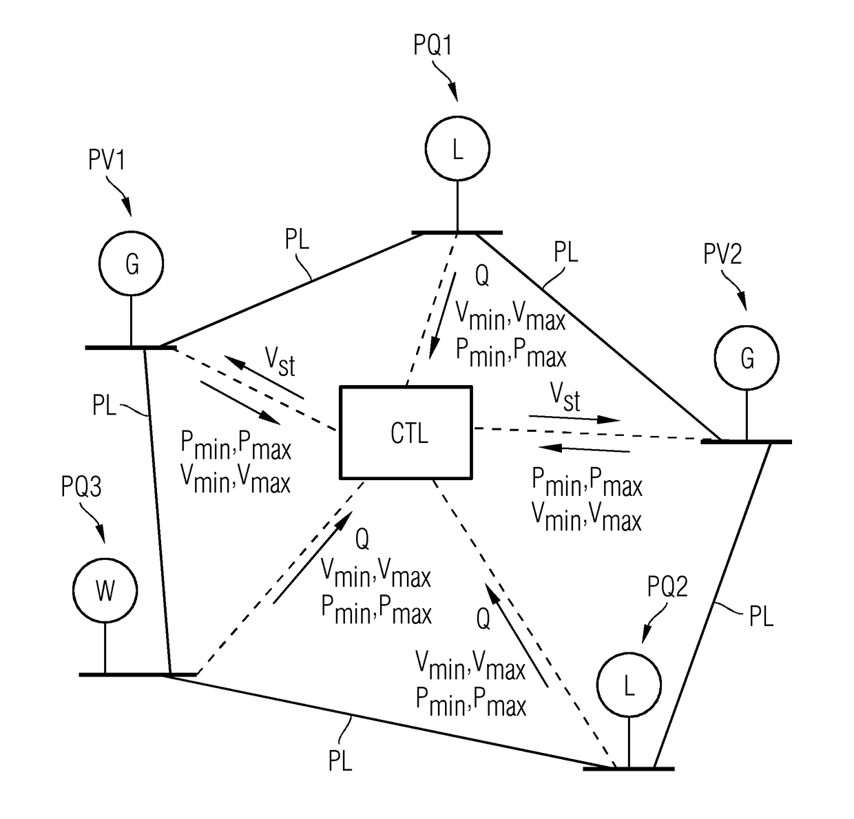
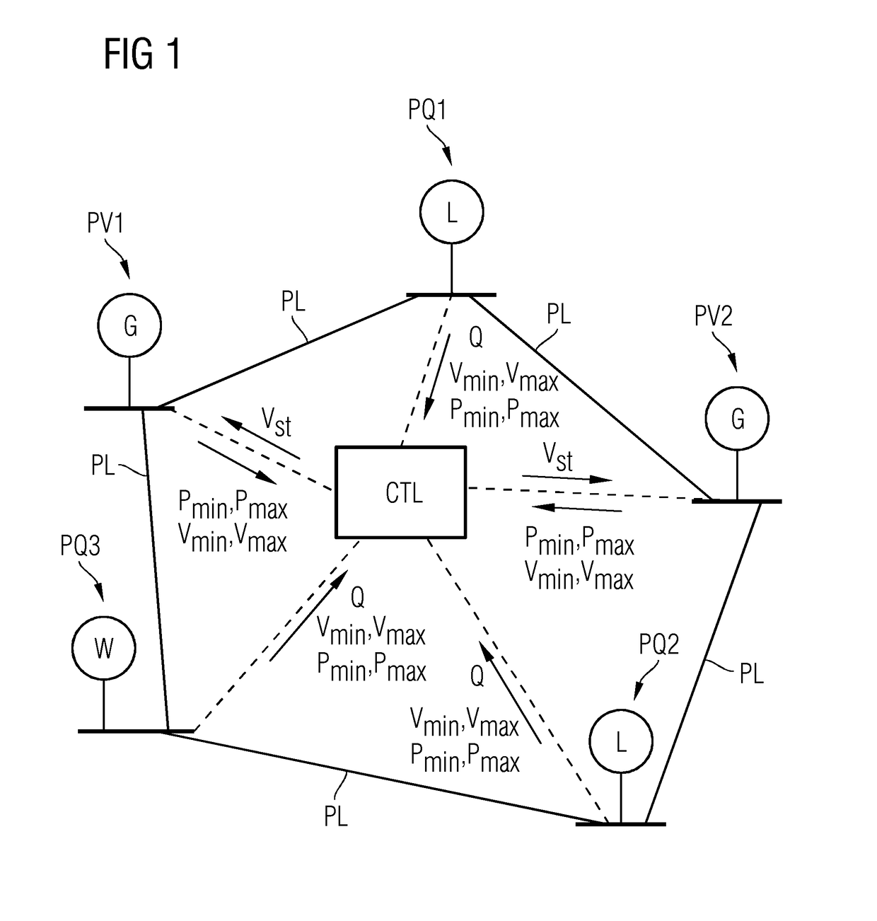
[0026]The controller CTL receives from each of the PQ buses PQ1 . . . PQ3 a value Q for the reactive power of the respective PQ bus. The reactive power value Q may also be a vector (e.g., a pair of parameters denoting a range such as a tolerance range for the reactive power of the respective PQ bus). This may be the case when controlling the voltage of PV buses in distribution grids described below.
[0027]The controller CTL inputs the received tolerance ranges specified by the Pmin, Pmax, vmin, and vmax for each bus and the received reactive power values Q for the PQ buses into a robust optimization process for a set of power flow equations, as described in detail below. The robust optimization process outputs a respective optimized voltage set point vst for each of the PV buses PV1 and PV2 so that the robust optimization constraints are satisfied. Each of the respective voltage set points vst is transmitted to the respective power generator G of the respective PV bus PV1 or PV2 in ...
first embodiment
[0056]According to a second exemplary embodiment, the power grid includes a distribution grid. In contrast to transmission grids the power lines may not be assumed to be purely inductive in distribution grids. With the power lines, the ratio rik / xik may even be close to 1 or above 1.
[0057]For distribution grids, the AC power flow equations (2) are the starting point. The rik / xik ratio is described by the phase of the complex impedance zik=rik+j*xik=zik*exp(j*Φik), where Φik=tan(xik / rik). It follows that rik / (rik2+xik2)=cos(Φik) / zik and xik / (rik2+xik2)=sin(Φik) / zik.
[0058]The following is obtained:
[0059](PiQi)=υi∑k∈𝒩s1zik(sinϕikcosϕik-cosϕiksinϕik)(υksin(θi-θk)υi-υkcos(θi-θk)).(16)
[0060]In order to find an appropriate solution of (16), the following simplifications are advantageous. The phase differences are rather small (e.g., it may be assumed that sin(θi−θk)≈θi−θk and cos(θi−θk)≈1). The variation of the voltages vi is negligible compared to the voltage differ...
PUM
 Abstract
Description
Claims
Application Information
 - R&D
- Intellectual Property
- Life Sciences
- Materials
- Tech Scout
- Unparalleled Data Quality
- Higher Quality Content
- 60% Fewer Hallucinations
Browse by: Latest US Patents, China's latest patents, Technical Efficacy Thesaurus, Application Domain, Technology Topic, Popular Technical Reports.
© 2025 PatSnap. All rights reserved.Legal|Privacy policy|Modern Slavery Act Transparency Statement|Sitemap|About US| Contact US: help@patsnap.com


