Gas purge apparatus, load port apparatus, installation stand for purging container, and gas purge method
a technology for gas purging and load port equipment, which is applied in the direction of cleaning processes and equipment, packaging under special atmospheric conditions, packaging, etc., and can solve problems such as placement failures
- Summary
- Abstract
- Description
- Claims
- Application Information
AI Technical Summary
Benefits of technology
Problems solved by technology
Method used
Image


Examples
first embodiment
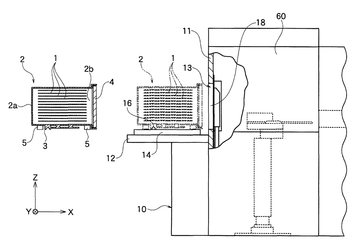
[0050]As shown in FIG. 1, a load port apparatus 10 according to one embodiment of the present invention is connected to a semiconductor processing apparatus 60. The load port apparatus 10 has an installation stand 12 and a movable table 14. The table 14 is movable in the X-axis direction on the installation stand 12. Note that, in the figures, the X-axis represents a moving direction of the table 14, the Z-axis represents a vertical direction, and the Y-axis represents a direction vertical to the X-axis and the Z-axis.
[0051]A sealed transport container 2 can be detachably placed on a top in the Z-axis direction of the table 14. The container 2 is made of a pot, a FOUP, or the like for transporting a plurality of wafers 1 while they are sealed and stored. The container 2 houses a casing 2a. A space for housing the wafers 1 to be processed is formed in the casing 2a. The casing 2a has an approximately box shape where an opening is formed on one of its surfaces in the horizontal direct...
second embodiment
[0091]A load port apparatus 10 having a gas purge apparatus according to the present embodiment has the same structure and effects as the first embodiment mentioned above except for the following matters that are different from the first embodiment mentioned above.
[0092]That is, in the present embodiment, a control means 80 shown in FIG. 3A controls a table moving mechanism not illustrated to return a sealed transport container 2 housing a plurality of processed wafers 1 to an undock position together with a table 14 as shown in FIG. 5A. The control means 80 shown in FIG. 3A detects the fact that the table 14 is moved to the undock position based on detection signals from load presence sensors 44a and 44b or detection signal from the table moving mechanism (Step S2 shown in FIG. 6B).
[0093]In this state, the above-mentioned bottom purge is still performed (Step S1 shown in FIG. 6B). Next, the control means 80 shown in FIG. 3A controls a control valve 23 as a gas feeding mechanism sho...
third embodiment
[0096]A load port apparatus 10 having a gas purge apparatus according to the present embodiment has the same structure and effects as the first embodiment mentioned above except for the following matters that are different from the first embodiment mentioned above.
[0097]That is, in the present embodiment, a control means 80 shown in FIG. 3A controls a table moving mechanism not illustrated to return a sealed transport container 2 housing a plurality of processed wafers 1 to an undock position together with a table 14 as shown in FIG. 5A. The control means 80 shown in FIG. 3A detects the fact that the table 14 is moved to the undock position based on detection signals from load presence sensors 44a and 44b or detection signal from the table moving mechanism (Step S2 shown in FIG. 6C).
[0098]In this state, the above-mentioned bottom purge is still performed (Step S1 shown in FIG. 6C). Next, the control means 80 shown in FIG. 3A controls a control valve 23 as a gas feeding mechanism sho...
PUM
 Abstract
Description
Claims
Application Information
 - R&D
- Intellectual Property
- Life Sciences
- Materials
- Tech Scout
- Unparalleled Data Quality
- Higher Quality Content
- 60% Fewer Hallucinations
Browse by: Latest US Patents, China's latest patents, Technical Efficacy Thesaurus, Application Domain, Technology Topic, Popular Technical Reports.
© 2025 PatSnap. All rights reserved.Legal|Privacy policy|Modern Slavery Act Transparency Statement|Sitemap|About US| Contact US: help@patsnap.com